Tag Archives: gauges

bowtie6‘s Custom Wiring – Inside the Cab

The last and final installment of the bowtie6‘s custom wiring takes us to the inside of the cab.  This will be the last on wiring – I know this is getting boring but I just want to show what can be done with a little creative thinking.

So what do we have here?

The picture above shows the quilted maple dash we made, it is mounted to an aluminium backing dash which in turn is bolted to the stock TR6 mounts.  The vent is fully operational with a bit of a twist – I’ll have to write about this later…

Behind all this you can see what I call the “cab” wiring.  Here are two spade fuse housings holding 7 of 8 fuses.  The ones on the left side are constant “on”; the ones on the right are switched.  In the middle you can see four relays.  Here is a closeup:

Why the missing fuse?  I am not completely done with the interior wiring and this circuit will be used at a later date when I add the final details to the inside:  fully operational door activated interior lighting.

Relays & Fuses

Four relays are mounted on this plate.  They control the following:

  • Heater and windshield wipers.
  • Turn signals – one relay controls “left”; the other controls “right”.
  • Parking lights.

As with all the other switches, the heater and windshield wiper switches make “ground”.  They in turn activate the electromagnet on the relays.  The B+ to the electromagnet side of the relays are fed by the fuses on either side.  I did not use circuit breakers here, I just used the spade fuese.

The turn signals are controlled by a stock TR6 turn signal stalk.  The turn signals feed goes through a “blinker” switch and from there, a wire is sent forward to control the front signals and a matching wire is sent rearward to the back turn signals.

The same process is done for the parking lights.  The parking lights and headlights are both controlled by a universal park-light/headlight switch.  I bought this from the same supplier I bought all the wiring from and is commonly used in street rods.

Two banks of fuses flank the relays.  The left ones are constant “ON” and supply power to the ignition switch, ECM and dash clock.  Yes, we have a clock in bowtie6!  I’ll have a writeup on the VDO gauges soon.

On the right, the fuses are switched “ON”.  These fuses supply such things are the control side to the relays as well as instrumentation lights and such.

In Summary

Once again, I guess you must be saying “this guy has a lot of time on his hands”.  Then again I wanted to make this flawless and 100% reliable.  I imagine you are asking yourself if this can be “seen”.  Well, I made sure to hide this as best as possible.  You have to get on your knees to see the fuse panel.  If you don’t know about it, you will never see it.  Finally it is mounted high enough that it does not get in the way of your knees and/or feet.

Another great advantage about all this is that all three panels are very easily accessible.  If for some reason a fuse blows it can be easily found and replaced.  When I built bowtie6 the first time, the fuse panel was in one central location.  It was VERY difficult to get to and was not easily serviceable.  I made sure to make it this time very “user friendly”.

And Then There is More…

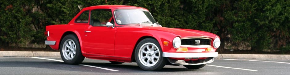
See anything “unusual” in the pictures above?  There are two small details that do not exist in a stock 1972 Triumph TR6.  See if you can spot them.

If not, stay tuned and there will be more about this soon…


Wiring Harness Milestone

After doing the tourist “thing” last weekend with wifey and not getting work done on bowtie6, this weekend was balls to the wall.  Fortunately, the planets were all in alignment and things worked out satisfactorily on the wiring front.

Since the wiring harness on bowtie6 is 100% custom (nothing “bought” here folks), this has taken quite a bit of time to design and build.  The premise has been to divide the car in three sections:

  • Engine Compartment:  circuit breakers, fuses and relays controlling the ECM, engine sensors, electric fan controller, headlights, main switch.
  • Cab Compartment:  fuses and relays controlling all instrumentation, heater fan motor, turn signals and switch, windshield wipers, headlight switch, parking lights switch, horn.
  • Trunk Compartment:  fuses and relays controlling all tail lights, fuel pump relay, fuel tank sending unit.

Yes, this is an unorthodox way to wire a car but is bulletproof.  All hard voltage switching is done with relays saving wear and tear on delicate switches.  All switches basically break ground and this makes for a very easy to diagnose system.

Well, today everything in the Cab Compartment and Engine Compartment was powered up and it all worked “the first time”.  No smoke, no blown fuses.  That’s the way we do things.

The ECOTEC has been fully functional for several weeks now.  We have let it idle for enough time to bring coolant up to operating temp and beyond.   This has enabled the electronic fan controller to kick in and run the SPAL fan enough to bring temps down and turn the controller and fan off.  The fan runs for about 30 seconds and shuts off.  It is cycling properly and this is the mark of a truly well designed system.

With today’s work, the parking lights were turned on; ditto for the headlights.  The floor controlled switch caused high beams to fire up as required and turn signals worked also flawlessly.  Inside, the wipers worked both in low and high speeds and the new heater motor’s three speeds worked as expected.

This leaves the trunk compartment to be done.  There will be a small fuse box along with a few relays to control all the rear lights and fuel pump.  Plans call for a small enclosure for all this and hopefully with a little luck, all wiring will be completed soon.

Fall is just around the corner and I just can’t wait to get bowtie6 back on the road…

Wiring Up the Gauges…

Moving along on the wiring, albeit slow.  Today, I spent 6 hours working on wiring up the instruments.  I was able to re-use some of the looms I made up the firs time, but had to make plenty of alterations along the way.  This is what it looks like from the backside:

The gauges are VDO Vision.  The have been great and are all electronic, compatible with the ECOTEC.  The speedo is programmable, so it is 100% dead nuts accurate.  The backing plate is aluminium and the front is made from quilted maple (I’ll have pics of the front in a later installment, once the dash is in place).

I realize this looks perhaps, unimpressive – but a huge amount of work has gone into making this up.  Every single connector has been soldered and shrink wrapped.  Since I wanted to make this so it can be removed easily, every circuit is connected to a “Weatherpack” connector.  This is why it has taken so long to make.

The following picture shows the dash area in bowtie6 before the dash goes in.

So…  What do we have here?

  • The heater has been replaced with an aftermarket unit.  The “original” heater unit I used to have developed a leak.  A little research found the unit pictured above which was a) cheaper and b) more efficient.  Plus it is able to withstand higher pressure.  This is desirable since it allows a high PSI cap on the radiator.
  • The transmission tunnel has been made from scratch to match the ECOTEC’s AISIN 5 speed gearbox.  It will be covered soon in Dynamat Extreme, just like the rest of bowtie6 has.
  • Finally, the piece de resistance:  If you look close, you can see the steering column is now fully adjustable.  Yes, a special mechanism has been made by my cousin Jim that allows the column to tilt with the flick of an adjustment bar.  I’ll have more on this later, once I get it all bolted back together.  Trick, huh?

This wiring effort has been very time consuming, but the end result will be fantastic.  There is a huge satisfaction from wiring up a car from scratch.  Not many people can do this type of work – it takes patience, but it sure is a lot of fun.