Tag Archives: electronics

Holley EFI Terminator Kit

I’m not very keen on endorsing products but, I will make an exception for the Holley EFI Terminator kit.  At my cousin Jim’s shop is Wayne’s 1956 Chevrolet 210, restored sometime in the 1980’s with a nice paint job, interior and a crate engine.  Wayne wanted something more reliable and fuel-efficient, so the old carburetor got ditched and work started to help bring this American icon back to life with modern EFI.  The centerpiece of all the new parts and today’s topic is the Holley Terminator EFI kit.

IMG_2458

Wayne’s 1956 Chevrolet 210

A new, fuel-injection compatible fuel tank with high pressure fuel pump, replaced the original tank.  The fuel pump kit included a special cylindrical shape sock made of a material that resembles a loofah sponge; this prevents sloshing and erratic fuel gauge readings.  Pretty cool stuff.  This was then plumed forward to the engine compartment with new stainless tubing.  Nice and tidy.

The Holley Terminator EFI kit comes packaged in a large box including all the bits needed to replace an aging carburetor.  This includes a device that resembles a 4 barrel carburetor but with all the necessary sensors needed by the EFI controller.

IMG_2473

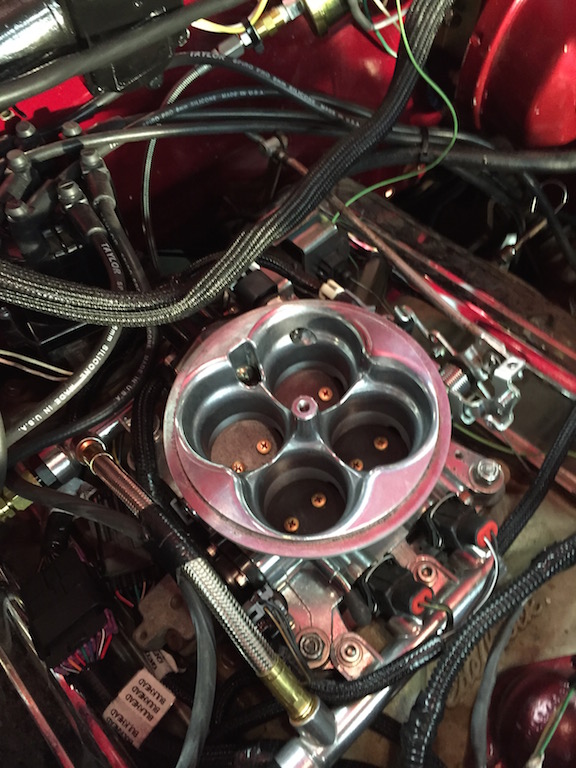
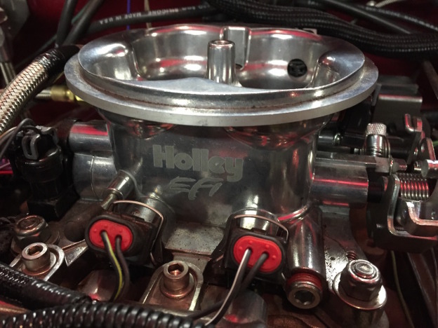
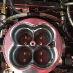
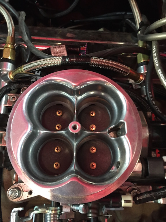
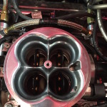
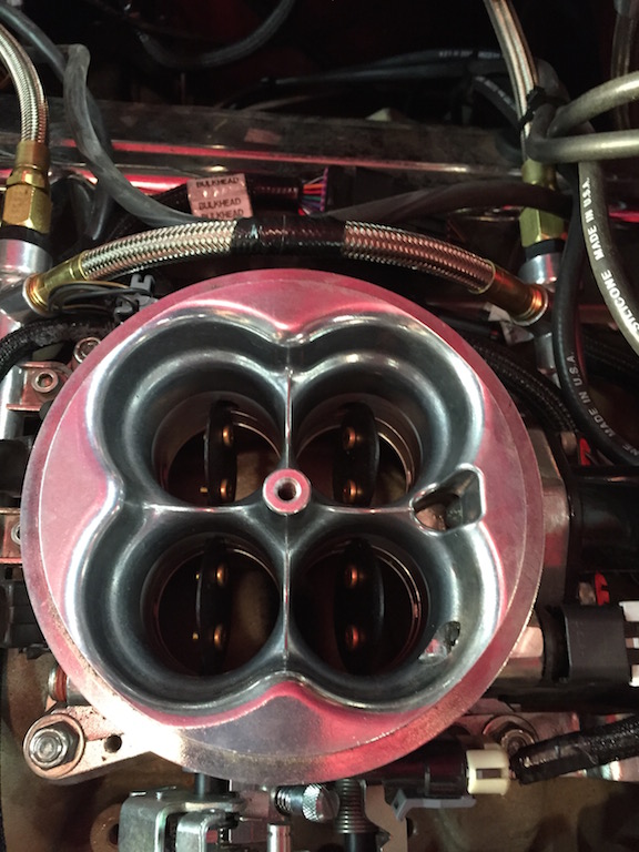
EFI Throttle body – note the 2 injectors and Throttle Position Sensor (TPS)

So essentially this is a Throttle Body Injection (TBI) kit.  You can see in this picture the four butterflies, the two fuel rails and two of the four injectors.  These injectors are special in that they spread a very fine mist below the butterflies that bust up fuel into a very fine fog.  There is a throttle position sensor (TPS), manifold absolute pressure sensor (MAP) and an idle air controller (IAC).  This whole affair sits on top of the intake manifold with no changes.

efi-controller

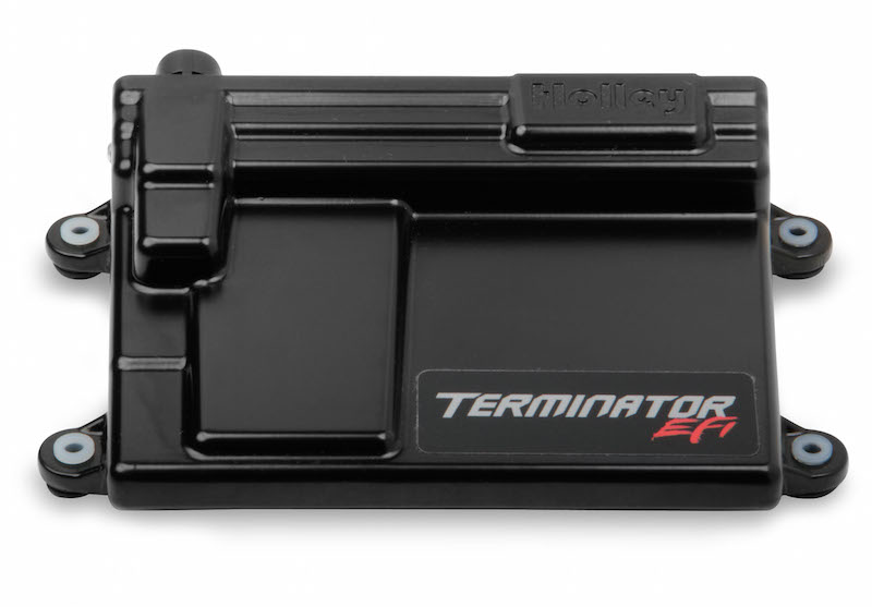
Holley Terminator EFI Controller (from the Holley website)

In the box is also a high quality wiring harness with first-class connectors and very clearly labeled wiring harness; wide band oxygen sensor and engine coolant temperature (ECT) sensor.  Several plastic bags are also included with just about any bolt and transmission linkage adapter one could ever need.  Finally the centerpiece of the kit:  the Terminator EFI controller and hand-held interface.  This is the same controller used by NASCRAP these days except that instead of four injectors, they use eight.  This controller can also be configured to run 4, 6, 8 or 10 injectors so this makes an excellent choice for other projects.
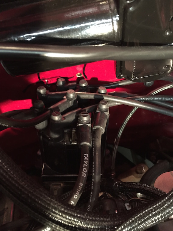
  :mrgreen:

IMG_2472

GM HEI distributor

The Terminator controller provides the ability to also control timing provided the a suitable distributor exists.  In this case, Jim installed a GM HEI distributor with new custom-cut spark plug wires.

Configuring the EFI Terminator and First Start-up

IMG_2474

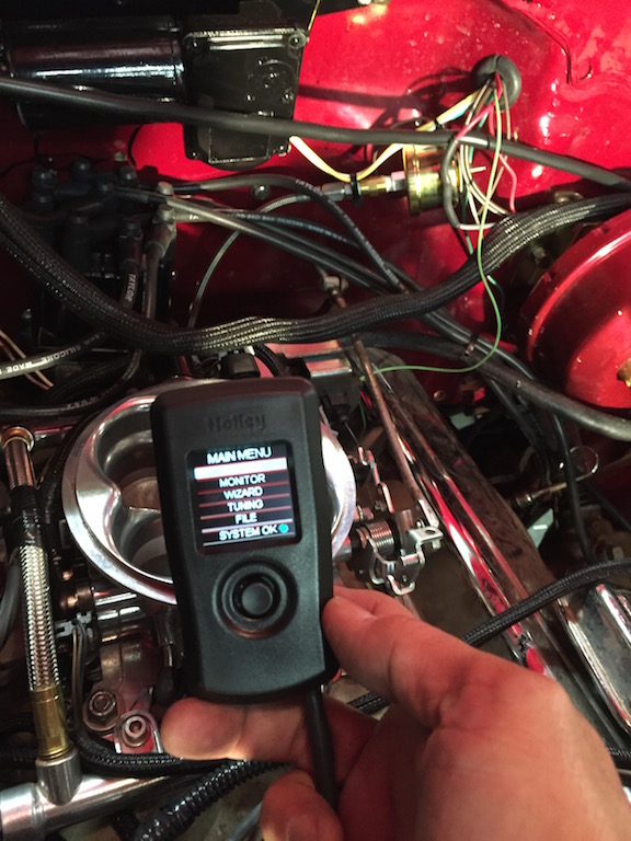
Holley EFI Terminator hand-held interface

This is where the Terminator kit really shines.  To kit comes with a joystick driven interface used to navigate a simple menu driven configuration.  The interface gets connected to a special port in the harness and enables the user to configure the controller as well as for monitoring real-time the sensors.  Prior to startup, the “Wizard” option enables input of engine-size, cam-profile and distributor type.

IMG_2476

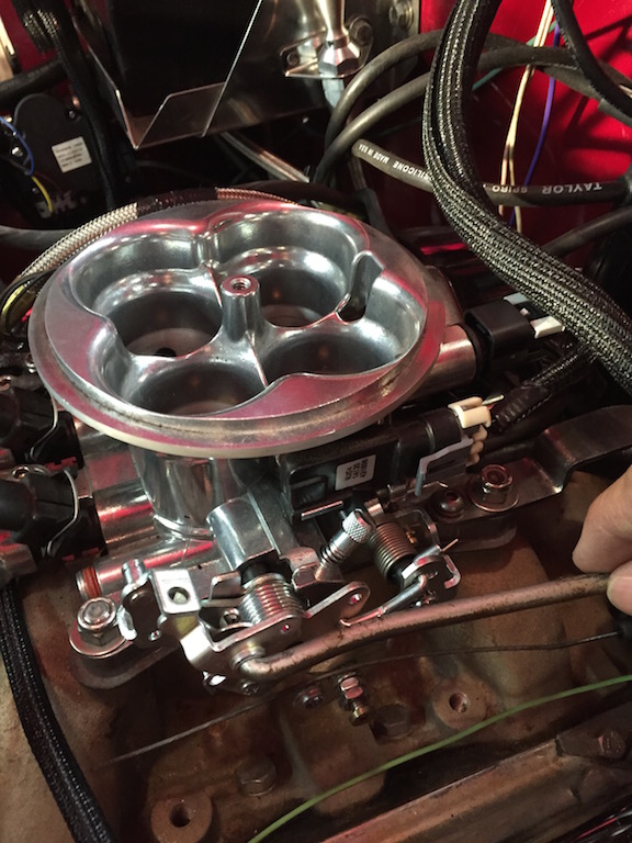
Throttle linkage and MAP sensor

Next, the Throttle Position Sensor (TPS) requires calibration.  Using another configuration menu option in the handheld interface, the throttle linkage gets cycled twice.  This action tells the controller the range of motion of the TPS.  The goal is to have the range of motion between 0% and 100% and this is easy to read in one of the “MONITOR” screens on the hand-held interface.

Once initial controller configuration is complete, it is time to start the engine.  Part of the built-in logic of the controller is the ability to “prime” the intake manifold by cycling the injectors depending on readings from all sensors.  This prevents flooding.

In our case, it took a few tries but eventually it fired off and ran very strong.  After a few minutes at idle the controller went to closed-loop.  Next on the configuration process we had to set timing.  This required revving the engine to approx 2000 RPM’s and shining a timing light.  The HEI distributor needed a minor adjustment enabling the RPM’s shown on the hand-held interface to match the reading on the crank.  At this point, the distributor could be locked in place.

Concluding initial setup required setting the idle speed.  This step calls for selecting the “MONITOR” option and reading the idle air controller (IAC) value at idle.  With a few tweaks of the butterfly adjustment screw we set the IAC value in accordance to the instructions.

Now What?

The next step requires taking the car out on the street.  We are not ready for that just yet because the interior must be put back, instruments installed and so forth.

Overall the Holley EFI Terminator kit is impressive.  Installation is very straightforward and the hand-held interface foolproof.  Yes, it is very “basic” (more on that in a minute) but it gets you going with very little confusion. One thing I did not like is the flimsy and diminutive plug used to connect the hand-held interface to the main harness.  It is very delicate – perhaps a more robust connector could have been used.

The documentation provided in this kit is excellent.  Somebody took their time writing this and Holley structured the start-up process in a very well-organized and detailed way.  There are plenty of pictures and diagrams especially of the menu-driven interface configs.  This instruction manual deserves careful reading because there is a lot of information.

Another very big plus about this system is the ability to control electric fans.  The controller is capable of running one or two electric fans.  The hand-held controller also allows setting the “ON” and “OFF” temperatures for fan operation.  In this installation because of space limitations there was room for only one fan.  The preset temperatures were left alone:  fans turn ON at 195 degrees and they go OFF at 180.

As if this were not enough, the controller can also be connected to a laptop!  The software is available for download from the Holley website and requires a USB cable.  In this case the cable gets connected directly to a port on the controller.  According to what I have read, this is how more complex and detailed configurations get selected.

I’ll have more details on how the rest of the configuration goes once the car is ready for the road.


Wiring Harness Milestone

After doing the tourist “thing” last weekend with wifey and not getting work done on bowtie6, this weekend was balls to the wall.  Fortunately, the planets were all in alignment and things worked out satisfactorily on the wiring front.

Since the wiring harness on bowtie6 is 100% custom (nothing “bought” here folks), this has taken quite a bit of time to design and build.  The premise has been to divide the car in three sections:

  • Engine Compartment:  circuit breakers, fuses and relays controlling the ECM, engine sensors, electric fan controller, headlights, main switch.
  • Cab Compartment:  fuses and relays controlling all instrumentation, heater fan motor, turn signals and switch, windshield wipers, headlight switch, parking lights switch, horn.
  • Trunk Compartment:  fuses and relays controlling all tail lights, fuel pump relay, fuel tank sending unit.

Yes, this is an unorthodox way to wire a car but is bulletproof.  All hard voltage switching is done with relays saving wear and tear on delicate switches.  All switches basically break ground and this makes for a very easy to diagnose system.

Well, today everything in the Cab Compartment and Engine Compartment was powered up and it all worked “the first time”.  No smoke, no blown fuses.  That’s the way we do things.

The ECOTEC has been fully functional for several weeks now.  We have let it idle for enough time to bring coolant up to operating temp and beyond.   This has enabled the electronic fan controller to kick in and run the SPAL fan enough to bring temps down and turn the controller and fan off.  The fan runs for about 30 seconds and shuts off.  It is cycling properly and this is the mark of a truly well designed system.

With today’s work, the parking lights were turned on; ditto for the headlights.  The floor controlled switch caused high beams to fire up as required and turn signals worked also flawlessly.  Inside, the wipers worked both in low and high speeds and the new heater motor’s three speeds worked as expected.

This leaves the trunk compartment to be done.  There will be a small fuse box along with a few relays to control all the rear lights and fuel pump.  Plans call for a small enclosure for all this and hopefully with a little luck, all wiring will be completed soon.

Fall is just around the corner and I just can’t wait to get bowtie6 back on the road…

bowtie6 Wiring – Part II –

Engine wiring is progressing right along,  albeit slow.  This part of building a car takes time!

So far the engine harness is complete.  All wires to the ECM have been accounted for and the main looms have been covered with crinkle tubing.  This tubing protects all wires and keeps things looking neat and professional.

Another engine bay picture showing the fuse box on the left, the coolant overflow tank, coolant lines and brake master cylinder and hydraulic clutch reservoir.  The coolant expansion tank is all hand made aluminium.  Missing from the coolant expansion tank is a small rubber hose going to an overflow tank behind the radiator; also hand made aluminium.  And yes, all the rubber coolant hoses are missing their clamps.  Just haven’t had a chance to get there yet!

Below, is a close up of the new fusebox.  On the bottom left, you see the new fuse box.  This is where all the relays, circuit breakers and fuses that control the engine compartment reside.  This is what it looks like:

So what do we have here?

Starting from the bottom:  below the box, hidden from view is a post that goes through the firewall.  This post is insulated with a Bakelite insulator.  From this post, wires feed battery power to the circuit breakers.  There are a total of seven circuit breakers; one for each relay.

Above the circuit breakers there are seven relays.  They are used as follows:

  1. Horn relay
  2. Electric Fan relay
  3. Headlight “on” relay
  4. Headlight high/low relay
  5. Starter relay
  6. Ignition relay
  7. Start button relay

Finally above all this are two banks of fuses.  To the left of the fuses is the electric fan controller and below that, the engine’s ECM.

Why so many relays?  The idea here is to use a relay for each device that requires high current, for example the electric engine fan.  The idea is to let the switches run low current controlling the electromagnet in each relay.

I know what you are going to say:  where are the turn signals and parking lights?  Yes, they have been left out.  Not by mistake, but by design.  Underneath the dash will be a smaller fuse box, containing fuses and four relays.  This is the part I’m working on now, and will be featured in the next installment…  Stay tuned.

bowtie6 Wiring – Part I –

Making a custom wiring harness is an interesting process.  It takes time and careful thought.  Is it for everyone?  No.  This is the second time I’ve wired bowtie6 and this time, I’ve applied several lessons learned from the first time.  Basically:  make things as easy as possible.

I’ve written previously about all this but I thought it would be nice to give a more in-depth view of the work I’ve done.  Maybe this might be of help for someone, so let me start with the engine.

To start with, a factory GM engine harness was sourced.  Contrary to popular belief, one does not need to buy a special harness (they are usually very expensive) to make an EFI engine run.  When properly modified a factory harness is an excellent starting point:  all the sensor plugs are there and the wire is of excellent quality.  Special care has to be taken however, when the harness is extracted from the donor car:  you want to make sure you get all the plugs and pigtails, including the fly-by-wire throttle pedal and its wiring pigtail.

I’ve seen many conversions where folks take an original harness and along with that, the instrument cluster, fuse box, firewall connectors, steering, etc.  This results in a cobbled up, complicated affair.  Why?

  • The donor car’s instrument cluster is kept because modern EFI will not get along with original, mechanical instruments.
  • The steering column is re-used because of the special vehicle anti-theft device that depends on the special tumbler and key to make the engine run.  This is commonly known as VATS – Vehicle Anti Theft System.
  • The original engine fuse box is retained because it is already made and it just “works”.

There is a better way.  In my case, the harness was sourced from an Ecotec powered vehicle: a Chevy HHR.  With the aid of the factory service manual for the Solstice/Sky, the harness was simplified by removing unnecessary circuits.  Many wires were shortened and by doing this the harness was greatly simplified and made to fit the engine bay of the TR6.  I did this because again, I’ve seen many conversions where people don’t resize the harness and this gives the engine compartment a very cluttered, busy look.  I’ve also seen conversions where great care has been taken to hide as much of the harness as possible.  This gives the installation a very professional, “factory” look which is not easy to do but if you take your time makes a huge difference.

In the case of the older six and eight cylinder engines the VATS can be disabled by adding a small, inexpensive aftermarket module or by having the ECM modified.  This solves the problem of having to use the original key, tumbler and steering column.  With the previous V6 in bowtie6, I used the aftermarket module.  It basically had a switched hot lead, a ground wire and a wire that was in turn spliced into a pin on the ECM.  With the Ecotec, we did not use a module instead we used software running on a laptop to disable the VATS circuit.

The ECM came from the same donor HHR the harness came from.  This gives a good starting point and is compatible with all the sensors, fly-by-wire throttle, etc of the “original” vehicle.  In my case, I’m running the 5 speed gearbox as fitted to the Solstice/Sky therefore the separate computer used to run the electronic automatic gearbox is removed – this was part of that “simplification” of the harness I mentioned previously.

After all the work of checking every wire for continuity, removing unnecessary wires and length alterations, several loose wires were left:

  • There is one unswitched hot lead that keeps the ECM alive.
  • There are a number of switched hot leads.  These control items such as the O2 sensor, injectors, coils, etc.
  • There are a number of ground wires that must be tied back to either the engine and consequently the engine must be grounded too..
  • The ECM controls the fuel pump.  Therefore there is a wire from the ECM that eventually goes to a relay that energizes the pump.

This pretty much wraps up the engine harness.  All this has been done so basically bowtie6‘s Ecotec is all wired up.  Not for the faint of heart, this process alone has taken many hours to accomplish.  There is not easy way out here, but the result is very cool indeed.

So what is left to do?  I’ve taken a different approach this time.  The first time I wired bowtie6, there was one central fusebox where all circuits originated from.  This was fine and dandy.  The fuse box was hidden behind the dash but the problem was twofold: 1) a huge amount of wires coming and going and 2) it was extremely hard to get to.  I once had a fuse blow and it was a hell of a job to find the blown fuse.

This time, the new harness is simpler and has been broken down into three main sections:

  1. Engine compartment:  this section will hold the main circuits managing the engine harness.  I’ve also included the headlights, horn and electric engine fan circuits.
  2. Occupant’s compartment:  basically inside the car.  A separate smaller fuse box will control all switches, instruments and heater.
  3. Trunk compartment:  the last small fuse box where the tail lights, reverse lights, fuel pump and fuel sending unit are all controlled.

In the next installment I’ll have more details about the engine compartment wiring which has been completed.  Stay tuned…

Wiring Harness

Tonight I started working on the engine wiring harness.  Doing an engine swap requires some sort of engine harness to be used along with the computer (ECM) in order to make the engine work.  This is the part where “old school” hot-rodders shudder and panic about.  This is also the part the trips up many folks attempting to run electronic fuel injection (EFI).

I’ve worked with my cousin Jim for the past 15 years perfecting the fine art of transforming a stock wiring harness into something that can be used to fully run a modern EFI engine in a classic car.  At first we worked on “throttle body” engines – basically a glorified carburetor but with the advantage of electronics.  These were the early EFI setups that offered much better economy than a plain carburetor but had a long way to go.  Throttle bodies evolved into individual injectors feeding each cylinder and more sophisticated ECM’s.

Through the years, we were able to adapt the L98 Tuned Port v8 with it’s distinctive intake with eight runners going to each cylinder.  As the L98’s became scarce we moved to LT1’s and LT4’s.  During this time, we also mastered the L32 V6 as originally fitted to bowtie6.  The next step was the LSx family of engines.  Currently we’ve focused on the ECOTEC engine as fitted in Jim’s TR4 and now my TR6.

The throttle body harnesses were the simplest.  No much really to figure out.  When we started using L98’s and LTx’s in Jaguar XJ6 and XJS conversions, at first we sourced the harnesses.  They were not cheap, so we took a stab at using original GM harnesses and cleaning them up.  If done properly they make an excellent harness however it takes some effort to figure them out.

This photo shows the harness from a wrecked 2.4 ECOTEC powered HHR.  The harness is basically all there; however it must be modified to work with the ECM and placement in the engine fitted to bowtie6.  This photo shows the harness after I had removed all the plastic casings protecting the harness.  This is done for several reason, among them exposing all circuits and it is easier to trace the wires to decide what needs removal.

We don’t use the original GM fusebox.  We also remove redundant ground wires and hot feeds, thus allowing the harness to be much simpler and easier to deal with.  Depending on what donor harness you use, certain pinouts on the ECM connectors must be relocated.  This is all done by using original GM Factory Service Manuals.

I’ll have more as the process takes shape.  This is actually a lot of fun however it is a little time consuming.  At the end of the day, it is a very rewarding feeling when the harness allows the engine to run.