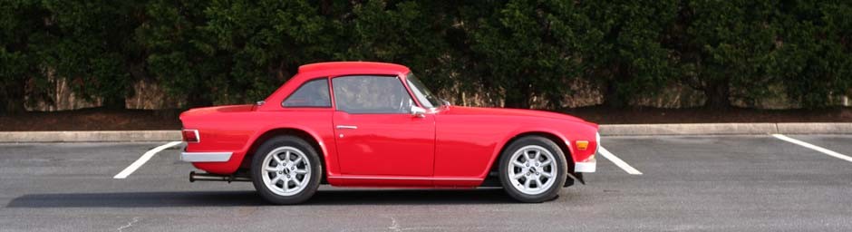
Been a long time since I’ve done any work on bowtie6. This little car is just like a trusted Timex watch – it takes a beating and keeps on ticking. This weekend I installed an upgrade: the other day, I came across a vendor that offered a phenolic intake spacer for the Ecotec. The advantage of a phenolic spacer is to help reduce heat transfer from the head into the intake manifold.
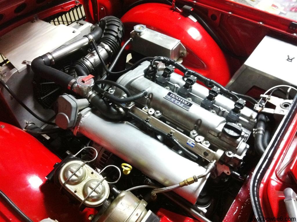
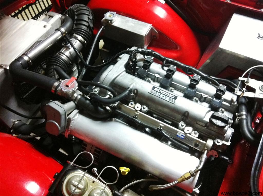
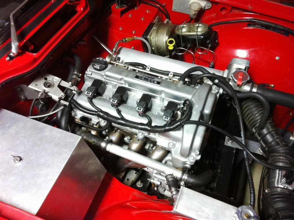
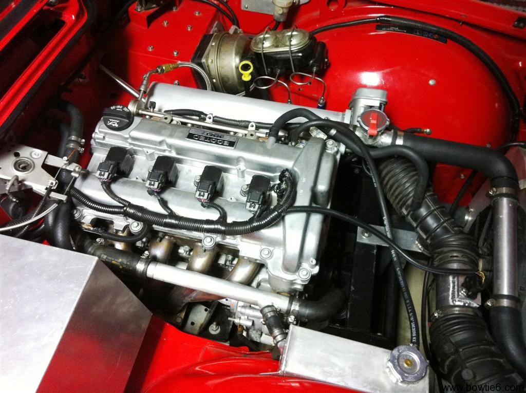
The intake manifold my cousin Jim made when we installed the Ecotec in bowtie6 is all aluminum (in case you want to know more about it, here is the link to a previous article with details about the custom intake). We did this because the original composite intake from the Solstice was just too large and would not fit because the steering shaft lives where the factory intake is attached to the head.
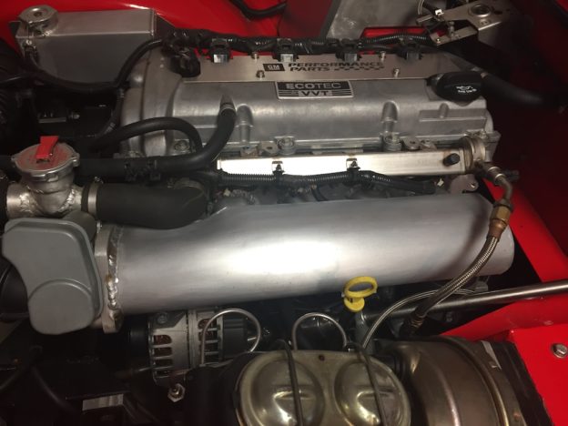
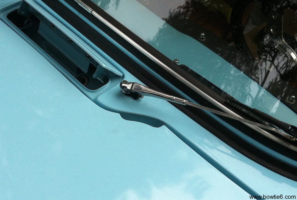
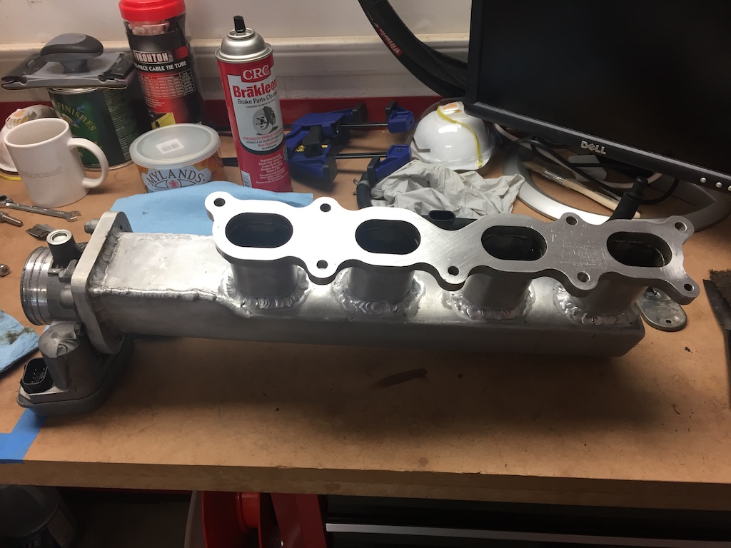
You can see the intake in today’s featured image above, and as you can imagine it gets a bit warm. I suppose the amount of time air hangs around the intake manifold is minimal, but any improvement would be helpful. So, I sent the $99 plus shipping for the phenolic spacer and a couple of days later, one of the brown trucks delivered this:
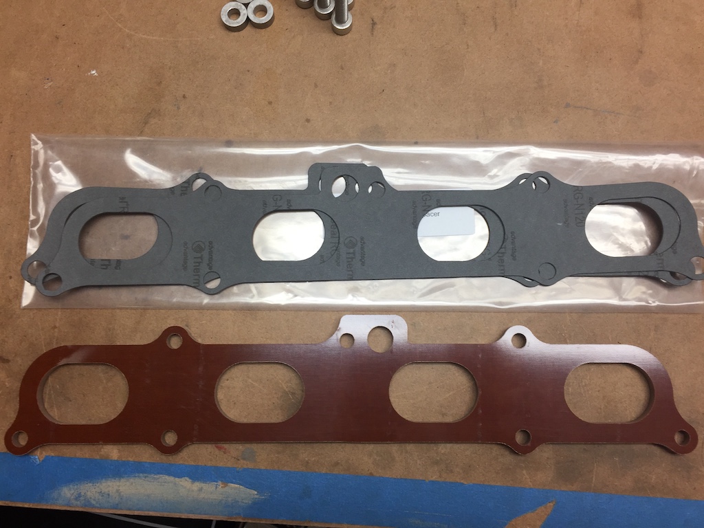
The phenolic spacer matches perfectly the GM intake manifold plate Jim used to build the custom intake and is exactly 1/4 inch wide. The “kit” comes with new gaskets and several replacement bolts. Sadly the bolts did not fit the head of the LE5. When I trial fitted all this, I noticed the factory bolts were about 1/4 inch too short (duh!), so I had to go find replacements. Fortunately the local NAPA store not far from home had them in stainless, no less. Torque settings on these bolts is not high, so the NAPA bolts worked just fine. Not bad for $8 and change.
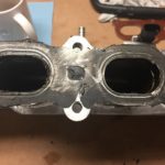
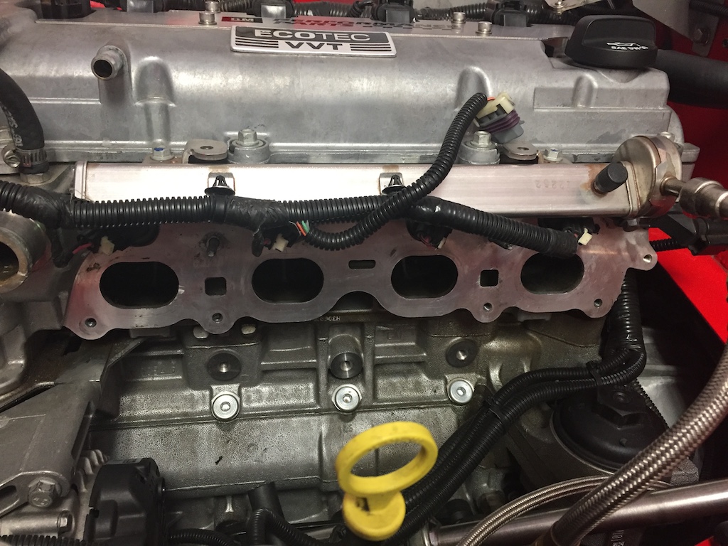
Taking the bolts out was a job! There is just no room. But, with a little patience and a few curse words, the manifold finally came out. I remember I had used RTV on the original metal gasket and was left with quite a bit to clean up. This is the intake manifold minutes after I had removed it.
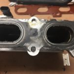
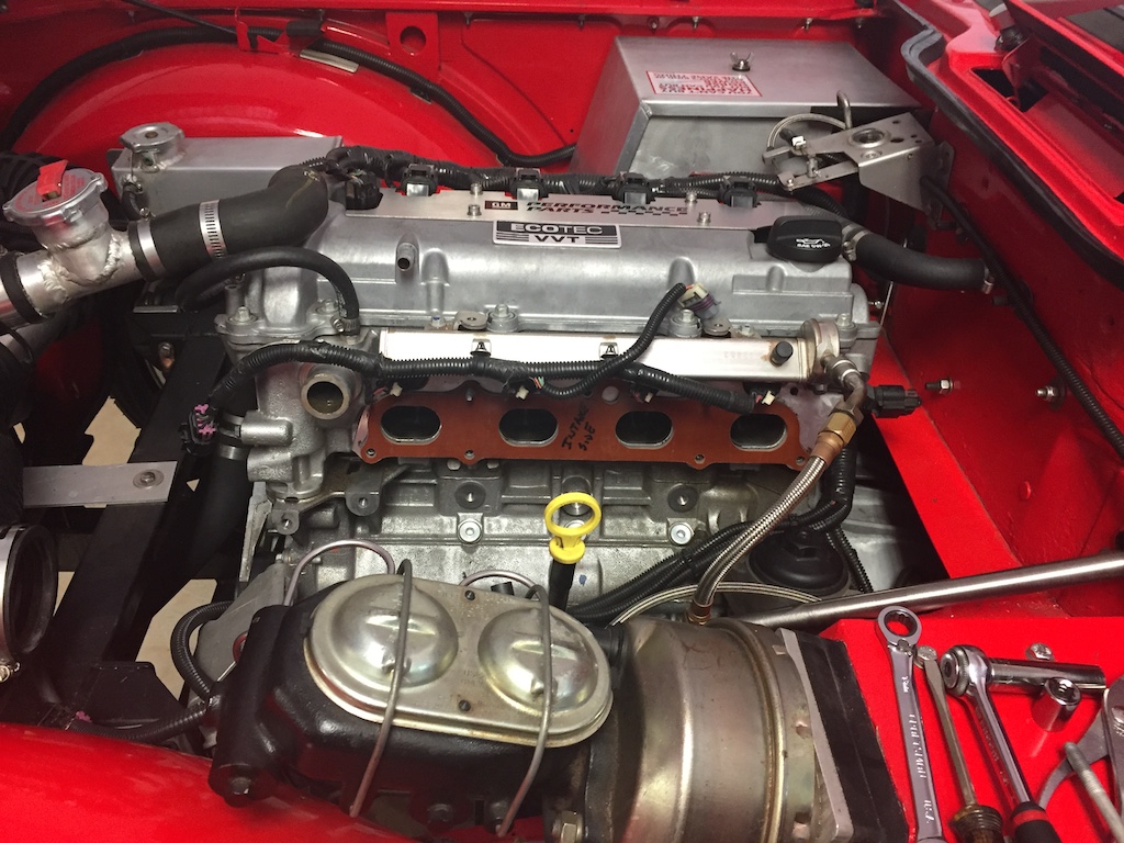
And here we have the other side. I had to remove the valve cover breather hose and the coolant hose. You can also see the alternator is still bolted to the block (more on this later).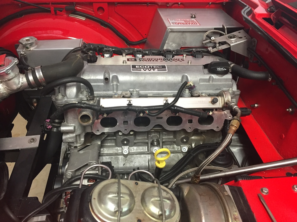 After a little elbow grease, the head and the intake came clean. From the mess in the the photos above, we have this:
Remember I mentioned the alternator being mounted? Well, after trial fitting the whole affair, I found there was no way in hell the bottom bolts could be reached without dropping the alternator. Here is what the phenolic spacer looks like in its new residence…
And here is a closeup…
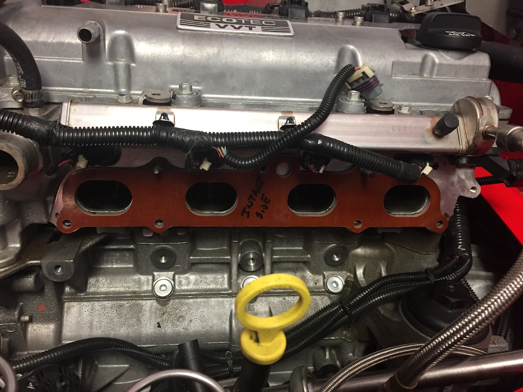
I had to mark the spacer with “block side” and “intake side” so I could line up the new gaskets in the right direction. Yes, they have a “side” – you can see that in the first picture above.
Then, the fun part: getting it all back together. As I mentioned the new bolts are about 1/4 longer, so it took some fiddling to get them lined up just right. I had to pay close attention to the gasket orientation and used a bit of gasket adhesive on the gasket face next to the block and intake. I left the faces that come in contact with the phenolic spacer dry because I did not want to risk damaging the phenolic material with the gasket adhesive material.
All that hard work, and you can’t even see the spacer! So much of bowtie6 is like this too.
And so, it is time to start the engine and go for a ride. But, we can’t have a good automotive project without the proverbial “oh shit” moment…
- gaskets lined up – check –
- bolts all accounted for – check –
- no extra parts (yeah!) – check –
- wiring connectors plugged up – check –
- alternator properly bolted – check –
- serpentine belt on – check –
- engine coolant hose – check –
- valve breather hose – check –
Get the keys, jump in and hit the ignition button. Nothing. Engine turned and turned, no fire. Strong smell of fuel.
Damn!
I retrace steps. Had to be something simple. Turns out the plug for the injector harness is the exact same size as the one for the electronic throttle body. I had them switched. No wonder. After swapping the electrical connectors, I tried to start the engine again. This time, a cloud of smoke came out the exhaust – she was pretty flooded so I decided to let the engine idle for a few minutes.
Finally, backed the car up and went for a short drive. I noticed no seat-of-the-pants improvement, but I did touch the intake when I returned and it felt much cooler. I have no idea if all this is going to make a difference but there is no big investment here. And yes, I would agree if you say that heat will still make it into the intake just by heat transferring through the bolts.
We shall see how this little experiment goes…
 On this 2023 July 4th weekend, bowtie6 got treated to a new fuel pressure regulator and braided lines. The old setup consisted of a GM style non-adjustable pressure regulator and a set of E85 resistant rubber fuel lines – I wrote an article about that (click here). I was never really pleased with the rubber hoses because the braided lines are much nicer and bullet proof. So I pulled the trigger and ordered parts for the new setup.
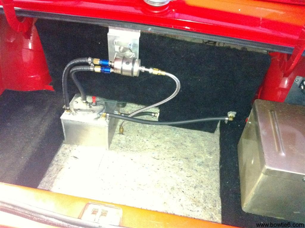
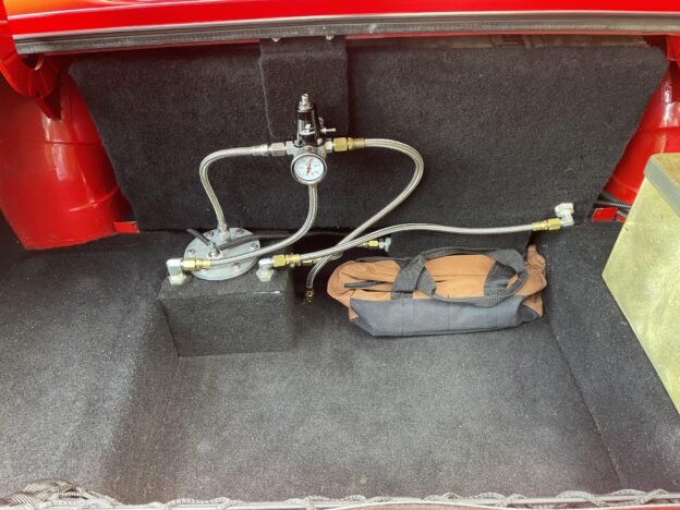
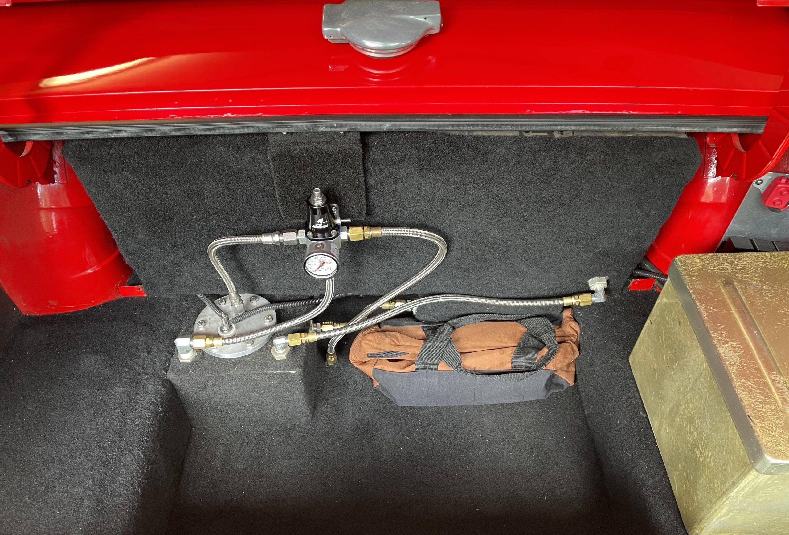
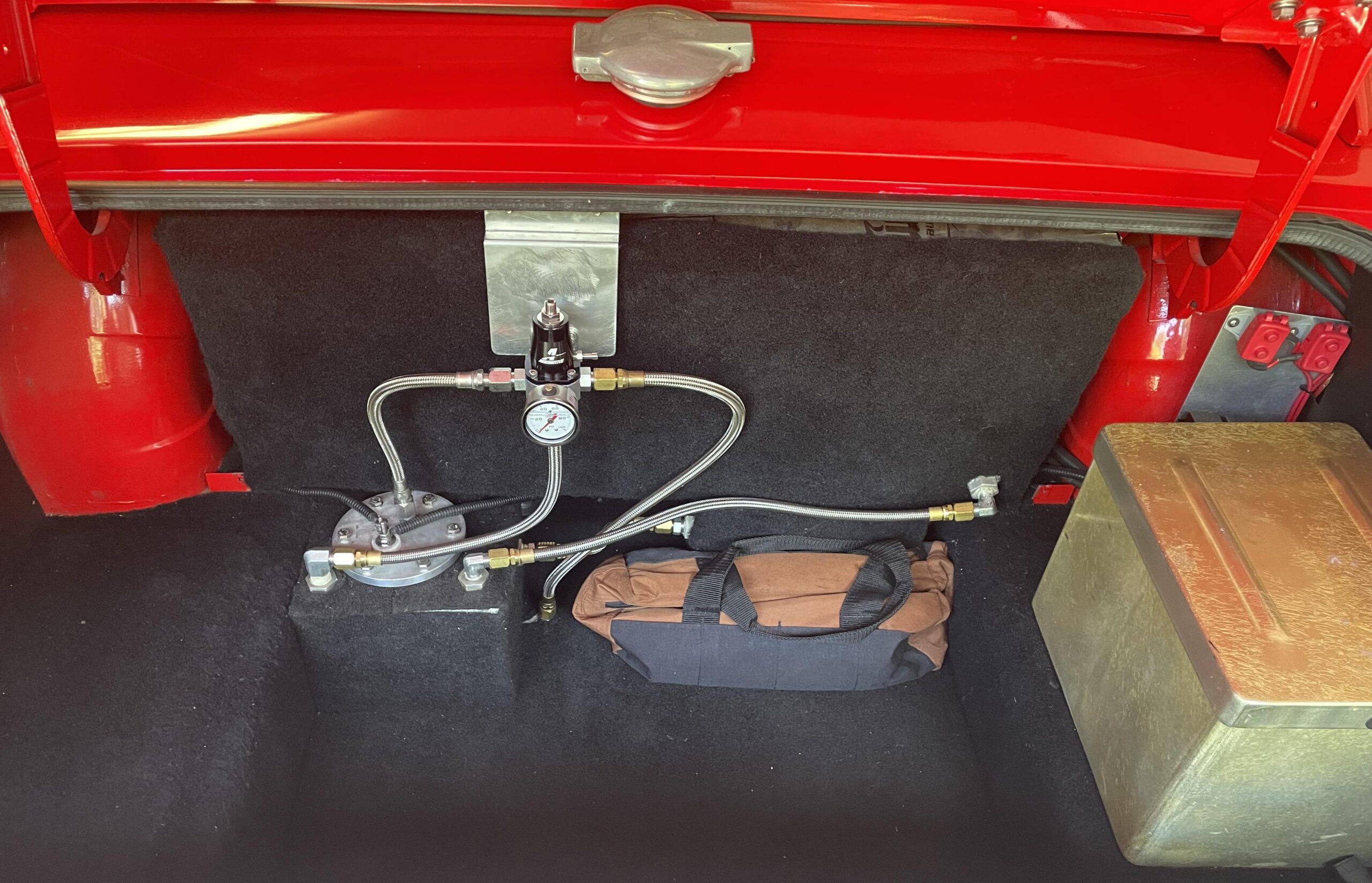 And this is what I mean…
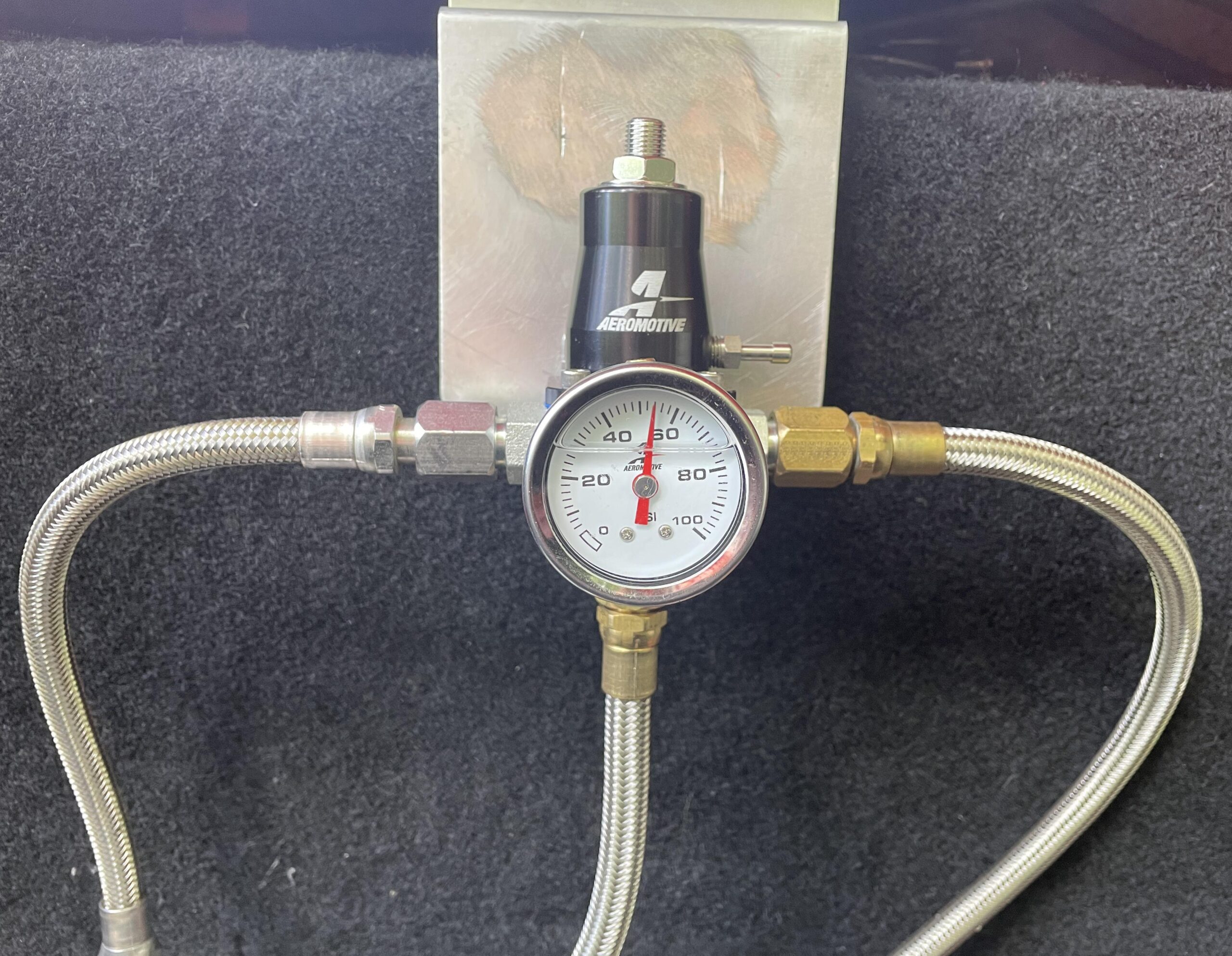 We had to cut the old mount and in the process the aluminum mount got scratched up pretty bad. I tried to sand this down but didn’t make much progress. Instead, why not just use some carpet material?
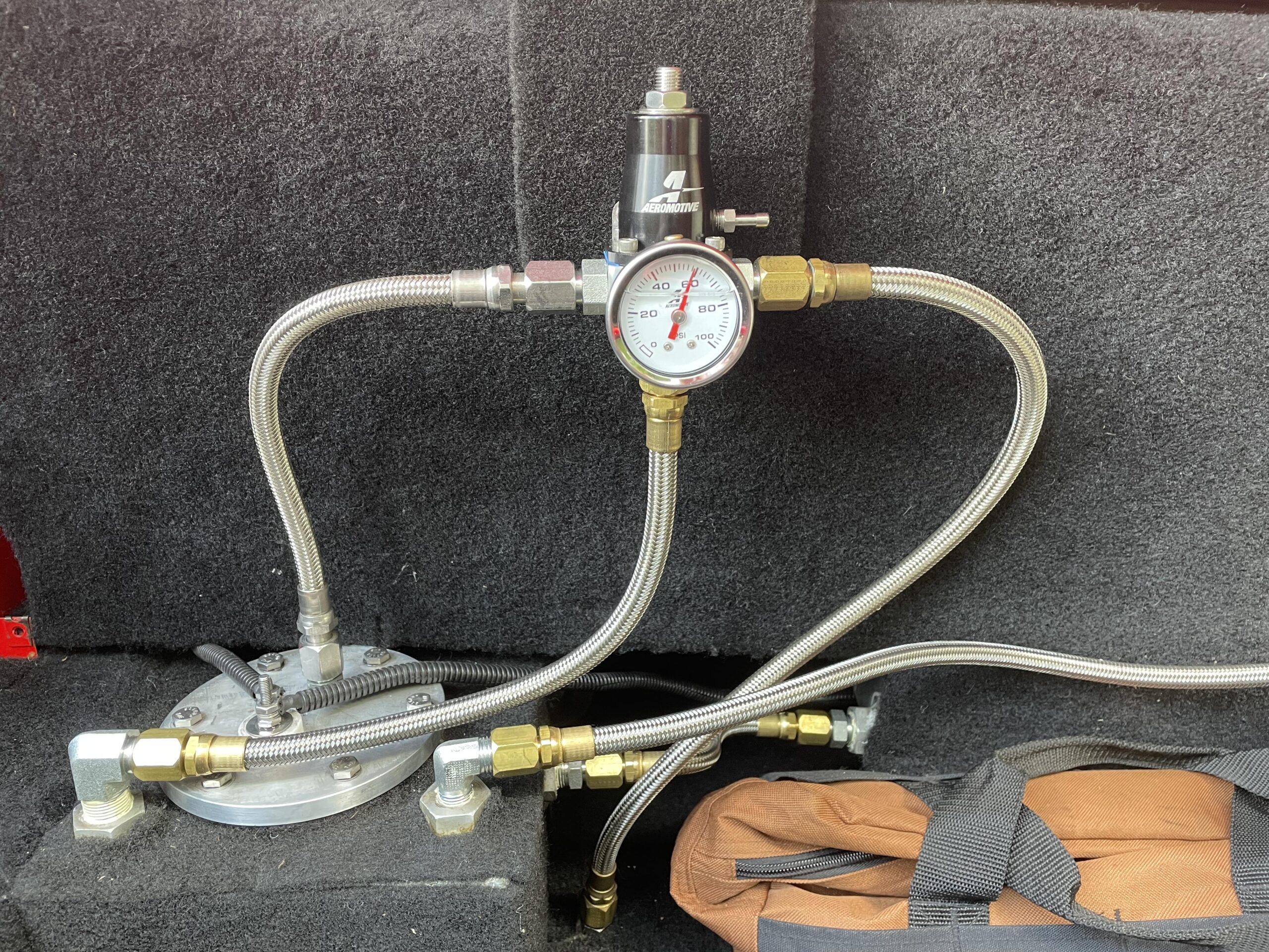
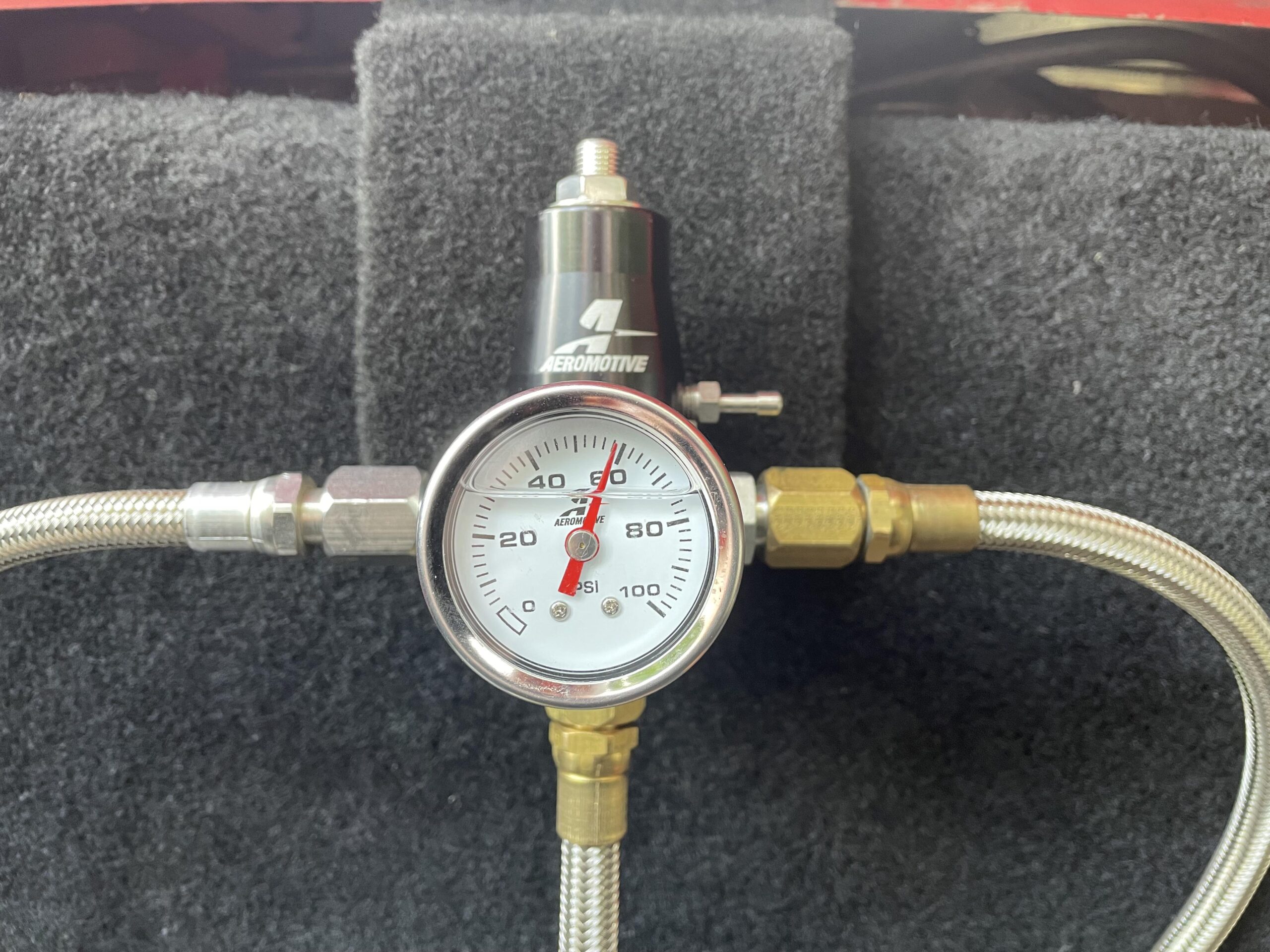 Ah! Much better! A keen eye will also notice the difference in pressure. I checked what the E67 PCM expected, and that was 58 lbs/in, so I bumped that up a bit.
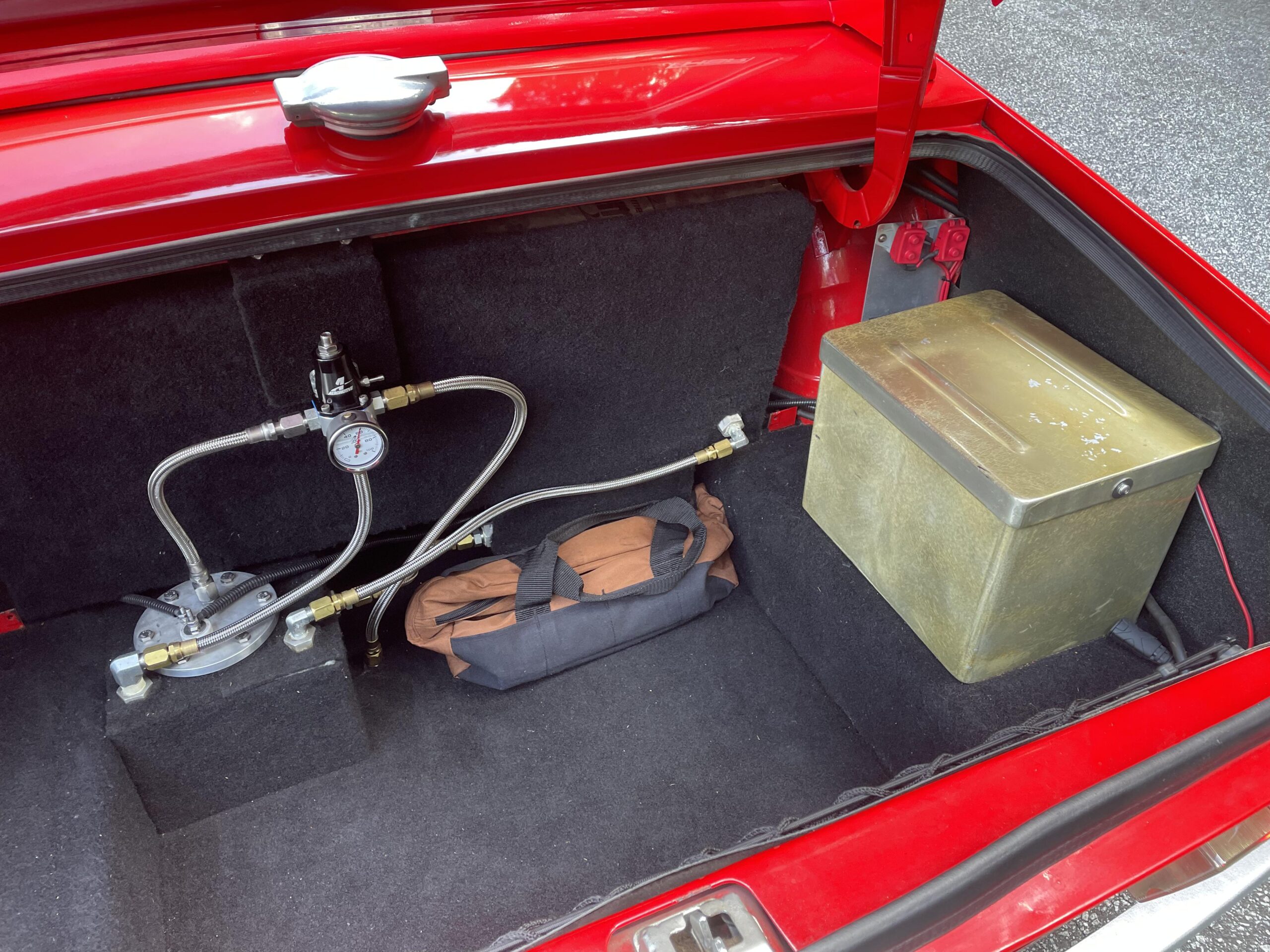
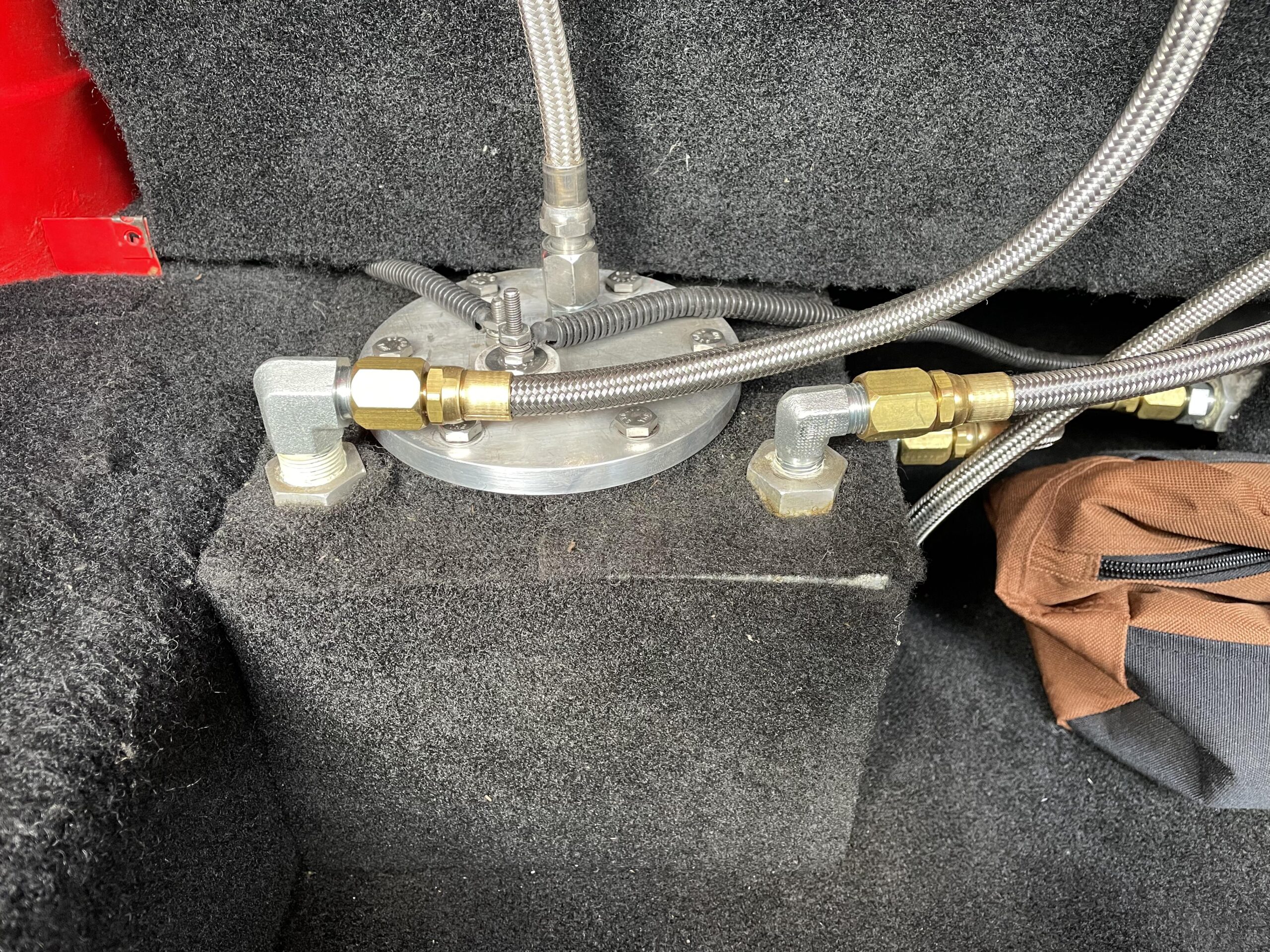
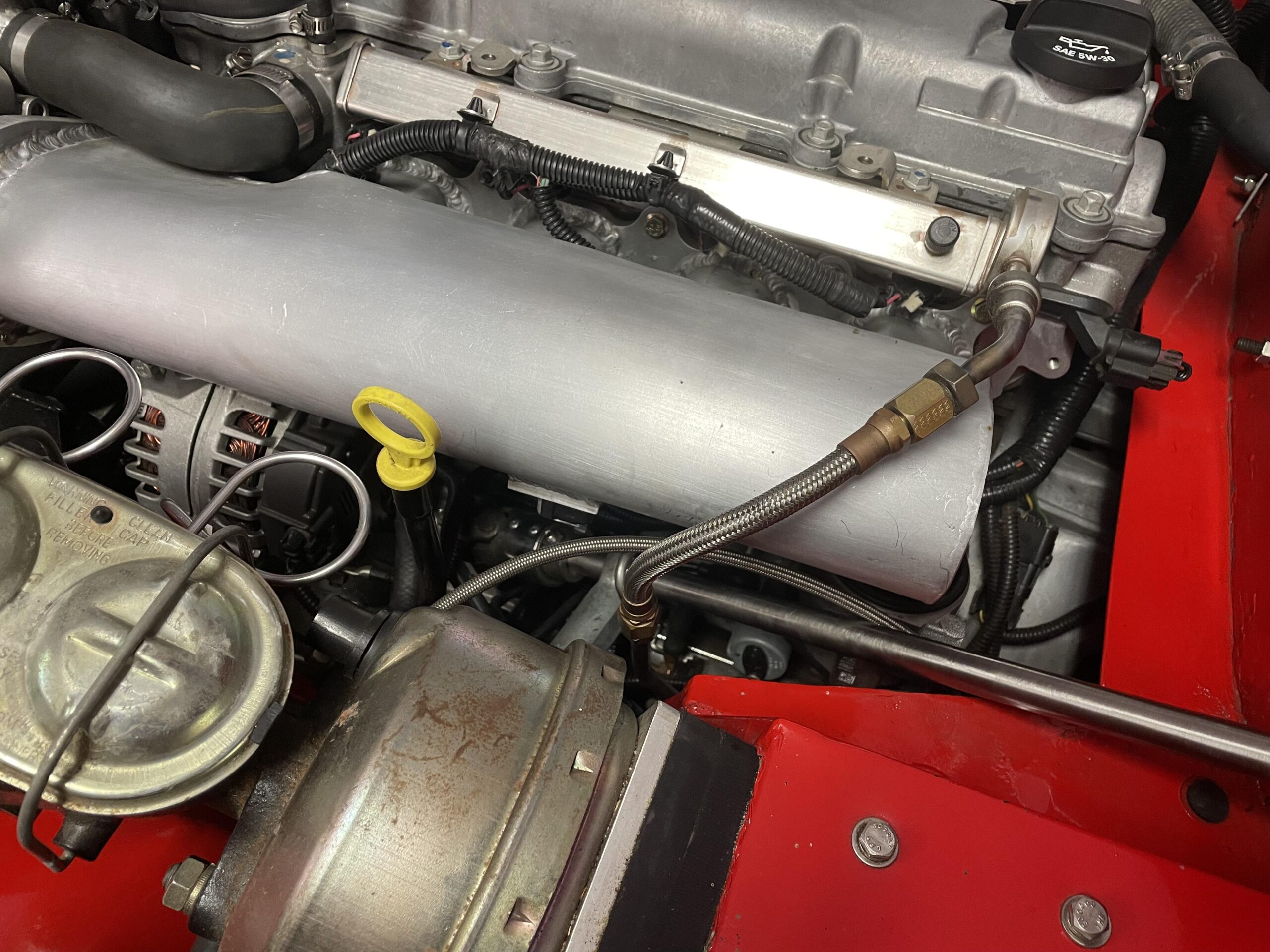
 And this is what the front looks like. This is another braided line going into the fuel rail. The other side connects to the stainless tubing under the frame of the car…