E67 PCM and the C1, C2, C3 plugs
In this article I’ll go over how to control electric cooling fans with an E67 PCM. I thought it might be nice to put this down in this long post in an attempt to help somebody else figure this out. But first a little background…
HPTuners is our preferred method of modifying the engine computers (PCM’s) on the engine swaps I’ve helped my cousin Jim with through the years. The tool consists of an interface that connects to the OBDII port on one side, and a USB adapter on a laptop. There is the Editor and Scanner software components that let you do pretty much anything you want. The proverbial catch is, there is so much to learn and not enough time…
I got an email from the good folks at HPTuners with an offer to upgrade our interface to the latest-and-greatest. Included with the deal were several credits, so why not? Well, this fired up my curiosity – once again – of getting bowtie6‘s PCM to control the SPAL electric cooling fan fitted to the radiator. I say “once again”, because I have been down this path before with sub-optimal results.
The First Attempt
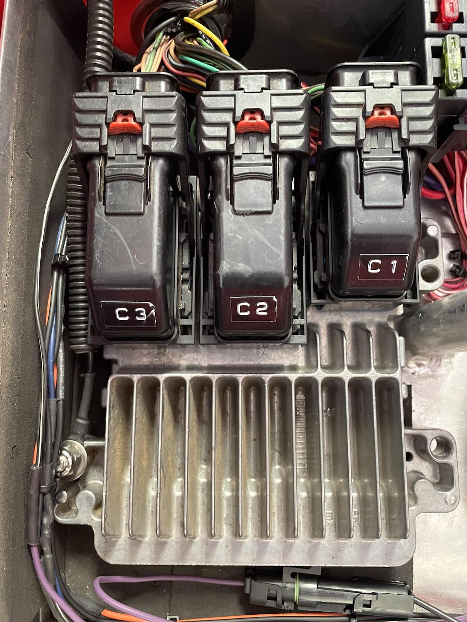
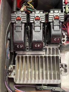
Engine management of the Solstice sourced ECOTEC in bowtie6 is handled by the E67 PCM. This PCM interacts with the engine by way of a modified Solstice wiring harness. By this I mean, many circuits have been removed, such as anything to do with Air Conditioning – for example, the wires and plugs for the compressor, pressure sensors etc. The wiring harness meets the PCM via 3 plugs: the C1 plug has 56 pins and the C2 and C3 have both 73 pins.
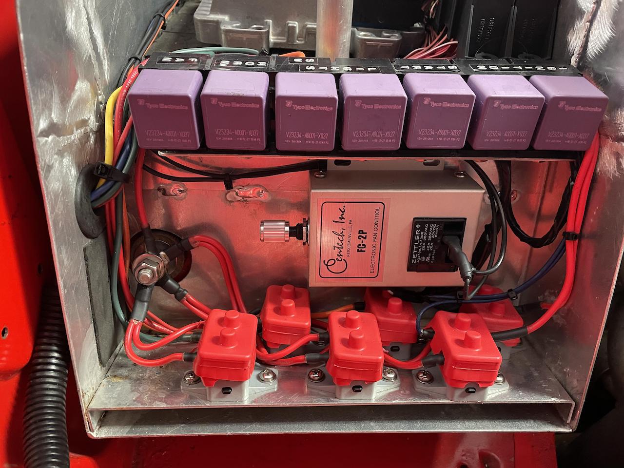
When Jim and I prepared the wiring harness, we removed the wires that handled the fan relays. We used a separate fan controller made by Centech as shown in the following picture:
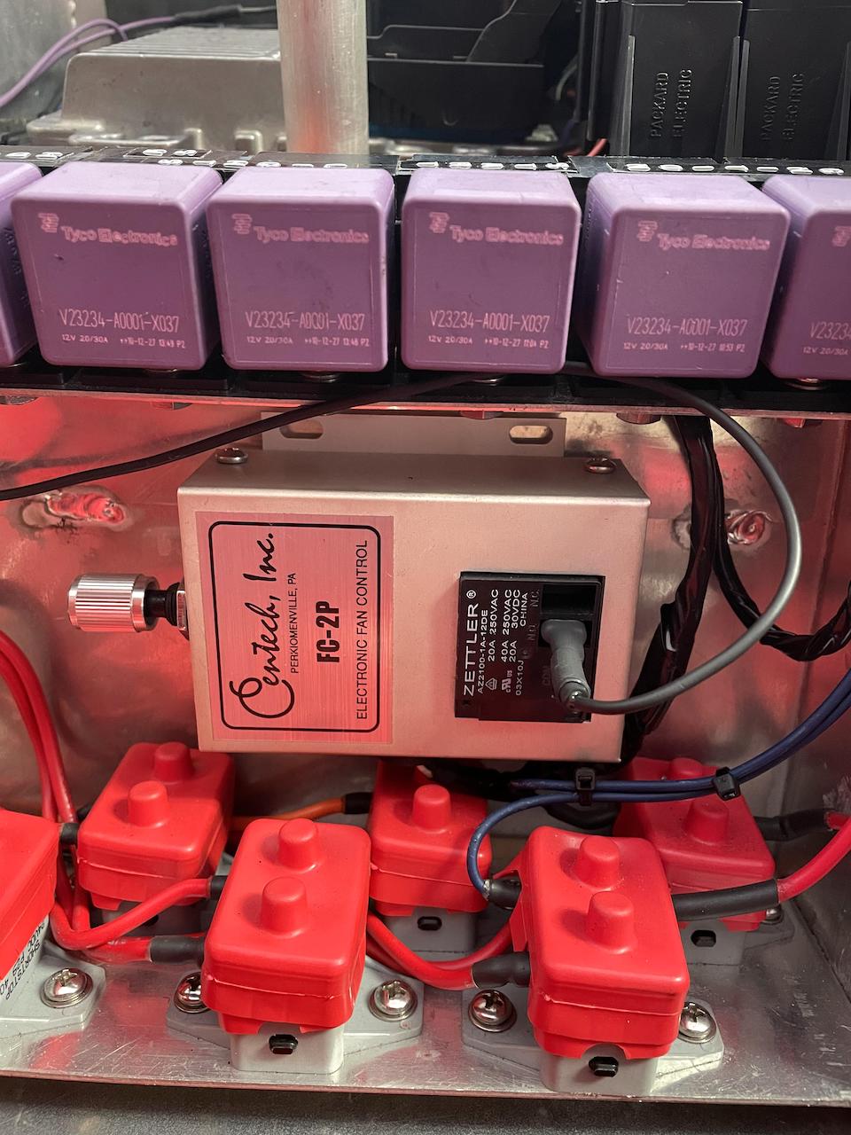
Centech cooling fan controller
The controller makes ground and is connected to the fan relay. The controller also receives a signal from an engine coolant temp sensor – NOT the one used by the PCM, instead Jim made a special adapter in the cooling system that houses the temp sensor for the Caltech device. in the picture above you can also see a small knob on the left, and that is where you control when the fan “starts”. So for all these years the fan has successfully been controlled by this device. But in the back of my mind, the PCM has the ability to do this so why not let that control the coolant fan?
The Solstice comes with two coolant fans controlled by two separate pins on the harness. The PCM makes ground, and in the stock setup they are connected to the control side of the fan relays. I have only one fan installed in bowtie6 so in theory, I figured I could use the FAN 1 wire, connect it to my fan relay and that would control the fan.

Fully shrouded SPAL high-speed cooling fan
And much to my surprise, the PCM as it reached the fan “ON” temp, would ramp up the engine by adding a few more RPM’s and after a short delay, the fan started. I thought “success!”: the fan ran, extracted heat from the radiator and I was able to see the engine coolant temp come down. But wait… The fan refused to stop.
All this was done many years ago, soon after we got bowtie6 on the road. I spent many hours trying to get this figured out, with no success. I posted on the forums but went nowhere. So, i gave up. I left the wire in the harness, going nowhere.
The Second Attempt
A few weeks ago, after the new HPTuners interface came in, I decided to re-visit this issue once again, so I gave it a go. I thought that surely, after all these years have passed there would be a solution somewhere on the web. Well, not really. I had to put together a few bits and pieces from several forums to find the solution: turns out the E67 PCM needs to know how fast the vehicle is going and factors that in controlling when the fans turn OFF.
When we installed the Solstice sourced LE5 ECOTEC, we also included the Solstice’s 5 speed AISIN manual gearbox. This gearbox was used in the Solstice/Sky as well as the Colorado pickup. On the side of the gearbox is a reluctor that sends out the vehicle speed signal (VSS) to the PCM. And this is done via a twisted pair of wires, a purple wire with the LOW signal and a yellow wire with the HIGH signal.
In my setup, I used the VSS signal to make the VDO speedo work. The VDO speedo requires a constant pulse and the VSS signal worked perfect. The VDO speedo has a “learn” mode where if you travel a mile it calibrates the pulses sent by the VSS and that translates to an accurate speed. Sure enough, all this worked and is accurate when checked with a GPS signal on my iPhone.
Since the fitted gearbox is a manual, my research indicated there is no need to send the VSS signal to the PCM. So we took out the VSS wires and pins when we modified the harness. This left the PCM clueless as to how fast the vehicle is traveling. And along with that, since the PCM had no frame of reference for speed, the fans would never shut off.
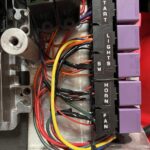
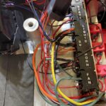
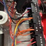
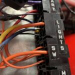
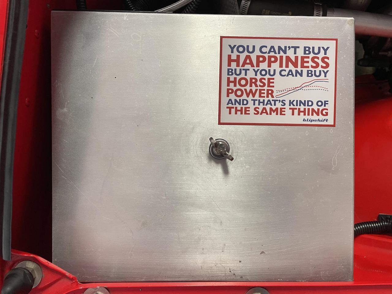
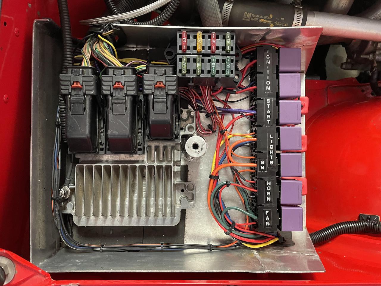
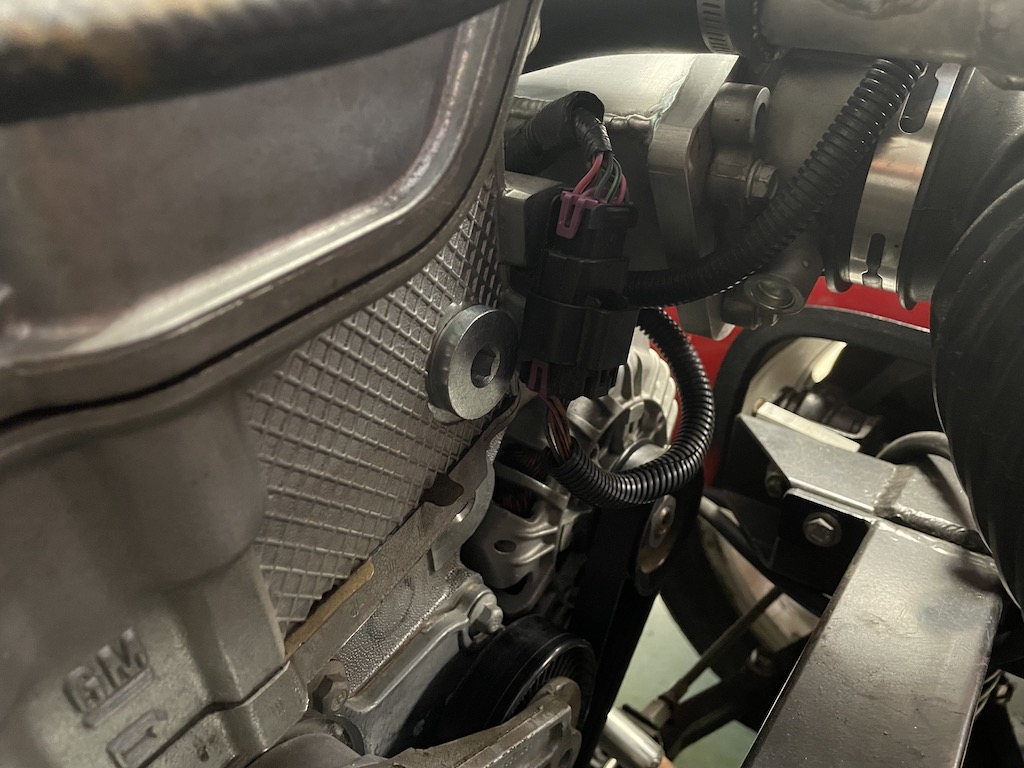
Solving this problem then, starts by splitting the signal from the VSS to a) feed the VDO speedo, and b) send the signal to the PCM. It took a little effort but I did just that and found the correct location in the correct connector to supply the VSS to the PCM. If you look at the photo of the PCM you will see I labeled with a Dymo tape, the three plugs – C1, C2, C3. Suffice to say, it is much easier to modify the harness on a workbench than on a car already installed! This can get confusing.
VSS Settings
I fired up the HPTuners Scanner and went for a drive. The speedo signal was now showing but it was off. And this comes as no surprise. The PCM still had the original Solstice settings. So the first change with the HPTuners Editor, was to enter the proper tire size and rear-end ratio. Once I entered that in the Editor and downloaded that to the PCM, speed now shows dead-nuts on the Scanner. I suppose for the purpose of the fans this might not be really necessary, but if we are going to go through all this trouble, might as well do it properly.
Fan Settings
The Solstice has two cooling fans. They are controlled by relays and the ground on the control side of the relays is connected to two pins on the PCM. One is labeled as “High Speed fan” and the second as “Low Speed fan”.
Since I did not want to go through all this trouble and still come up empty handed, wired up a spare relay base and relay, and connected a test light so I could make sure I had the right fan wire coming out of the PCM. Using the HPTuners Scanner, there is a page where one can manually command a fan to come ON or OFF. And sure enough, the test light came on when the high-speed fan was selected. Next, I removed the test light setup and the fan relay instead. I did the dry-run again and this time the relay clicked and the fan started up.
Now to the fun part. First, the main Fans page:
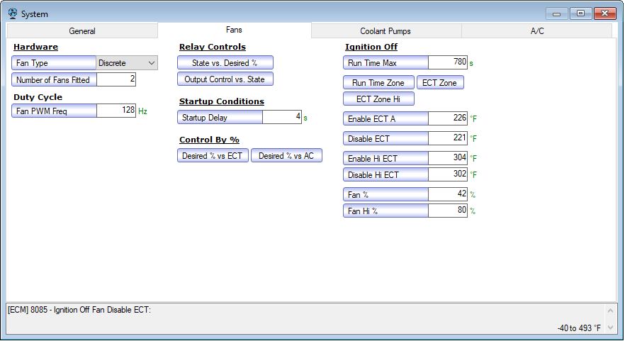
Fan Settings
For starters, the Fan Type: I have left the fan as “Discrete”. The other option is Pulse Width Modulated (PWM). The discrete fan settings is used when the PCM is controlling a relay for an Off/On type setting. The PWM setting is for when a fan that can run at different speeds is installed. For the purpose of this post, I am working with a relay to control the fan.
Also, note where you can select the Number of Fans Fitted. In this case, I left it at two. More on this later.
Next, comes the confusing part. The E67 PCM has to two tables that control fan behavior: Fan Desired Pct vs Engine Coolant Temp (ECT) and Fan State Transition Desired % vs Current State:
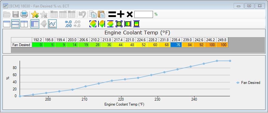
Fan Desired Pct vs Engine Coolant Temp (ECT)
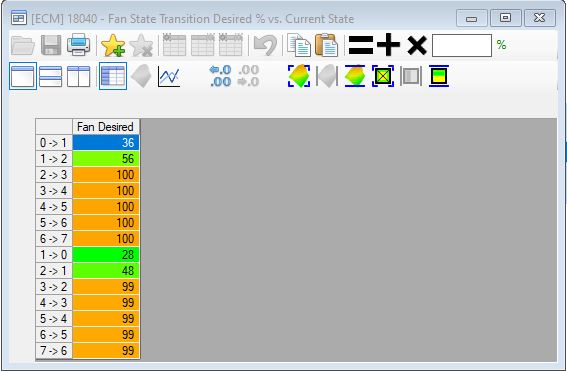
Fan State Transition Desired Pct vs Current State
The top chart is used to set the coolant temp required to turn the fan ON or OFF. The bottom chart is used to set when the fan should turn ON or OFF. Confusing? Join the club.
OK – this is what I have so far: I have left the Number of Fans Fitted at two. Therefore this means we have a “Low speed” fan and a “High speed” fan as far as the computer knows. I wired the “Low speed” ground to the relay control side. Since I don’t have a second fan, the “High Speed” fan is irrelevant.
The “ON” conditions:
- By reading the charts above, the “Low speed” fan transitions to the ON position with a Fan Desired setting of 36 (the 0->1) and that translates to ~214 degrees on the top chart.
- If I had a second fan wired in, then the second fan would be ON at Fan Desired setting of 56 (1->2) and that translates to ~225 degrees on the top chart.
And now the “OFF” conditions:
- If I had a second fan wiring in, the second “High Speed” would be OFF at Fan Desired setting of 48 (2->1) and that translates to around ~221 degrees on the top chart.
- Finally the “Low Speed” fan (which is fitted) turns OFF at Fan Desired setting 28 (1->0) and that is ~210.
BUT remember, the only time the fan actually turns OFF is when the vehicle is moving. So at a red light, the fan would continue to run even though coolant might be below ~210 degrees. It is only when the VSS sends a signal the vehicle is traveling at ~15-20 mph that the fan will actually turn OFF once the ~210 threshold has been met.
In Summary
I have been able to successfully test the above settings. The one SPAL fan does kick in at roughly ~214 degrees. Once engine coolant reaches 214, I can audibly confirm the engine speeds up slightly and then after a slight delay, the fan kicks in. If you look at the Fan Settings screenshot, you can see there is a Startup Delay setting. I compared that to the settings on my 2014 Camaro SS with an L99 V8 (I know, apples and oranges) and for the Camaro, the delay is zero. But duh, double the cylinders so I suppose in that case it does not matter. For an engine with half the cylinders, this gives it a few seconds to “ramp up” before the hit of the fan kicking in.
The next experiment will be to play with the Number of Fans Fitted setting. I ran into self-inflicted error when I wired up the single fan: I wired it as the “High Speed” fan. Clearly that was a mistake because the first fan to kick in is the “Low Speed”. Wha happened when I did this was the fan would turn ON after coolant had reached ~225 degrees. So the take-away here when using only ONE fan, is to use the “Low Speed” pinout to make ground in the relay control circuit.
This is a very long-winded version of my experiment. And I know, might be a little confusing. Especially the last two charts above. I am still trying to wrap my head around all this.
But what about PWM?
Ultimately this is where we want to be. I had a very long talk with my friend Michael Y. and we talked about PWM fans. Michael has extensive knowledge of this and I tried to draw from his experience in the matter. Perhaps we might get lucky and he might give some words of advice in the replies section.
The big advantage of the PWM fan would be to try to keep coolant temps consistent, rather than the way I have them in my purely ON/OFF settings. In my case, the primary goal is to keep the engine from overheating at stop-and-go traffic. But, it ultimately it would be nice to have the one SPAL fan running as a variable speed setup.
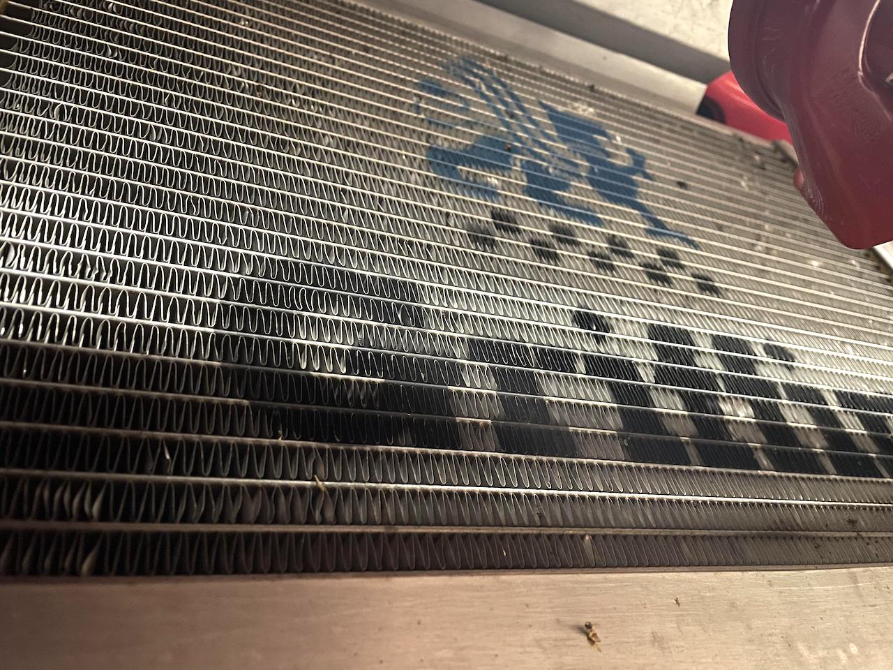
Griffin aluminum radiator – image taken from the bottom of the radiator facing forward
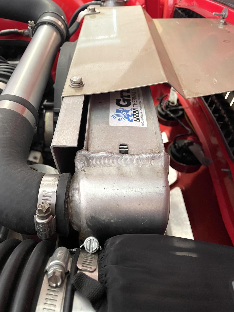
Width of Griffin radiator
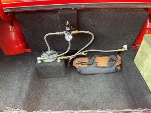
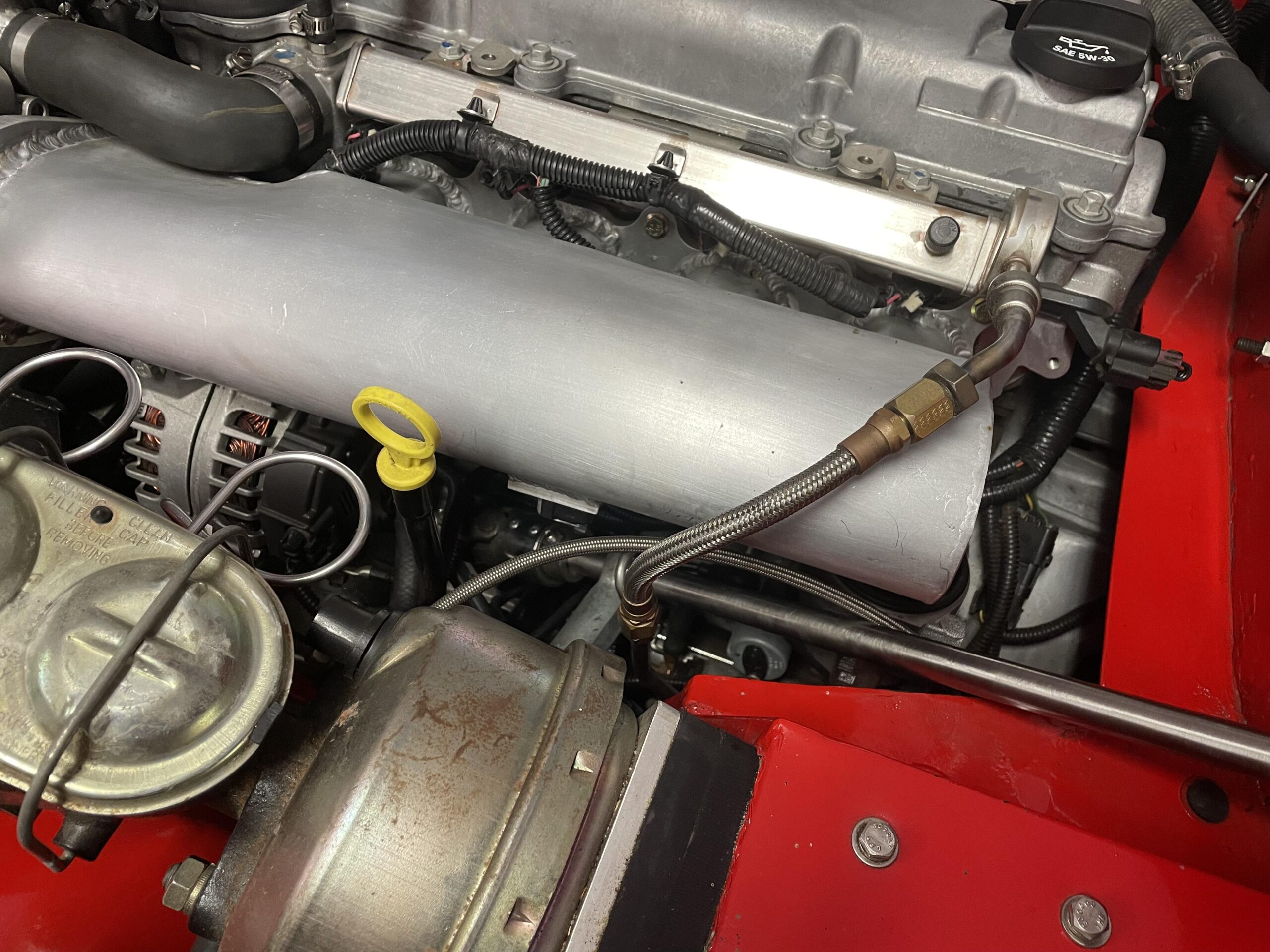
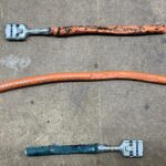
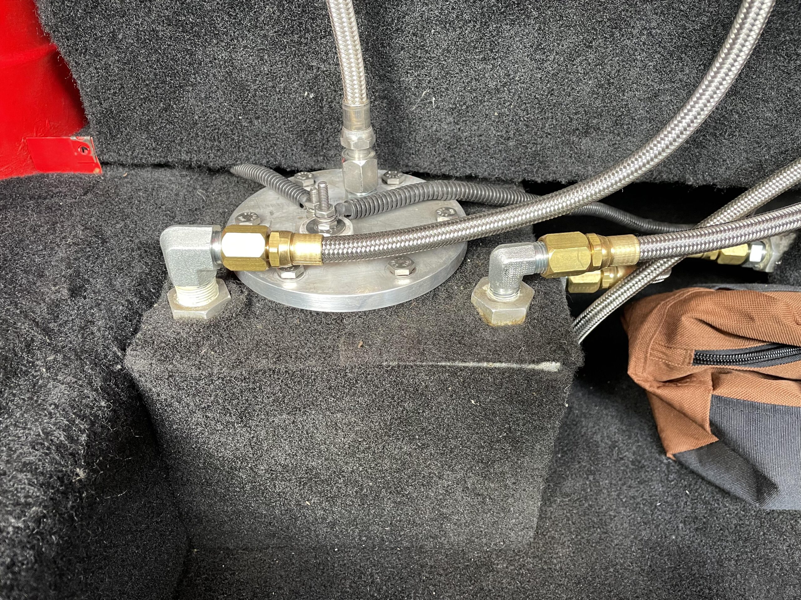
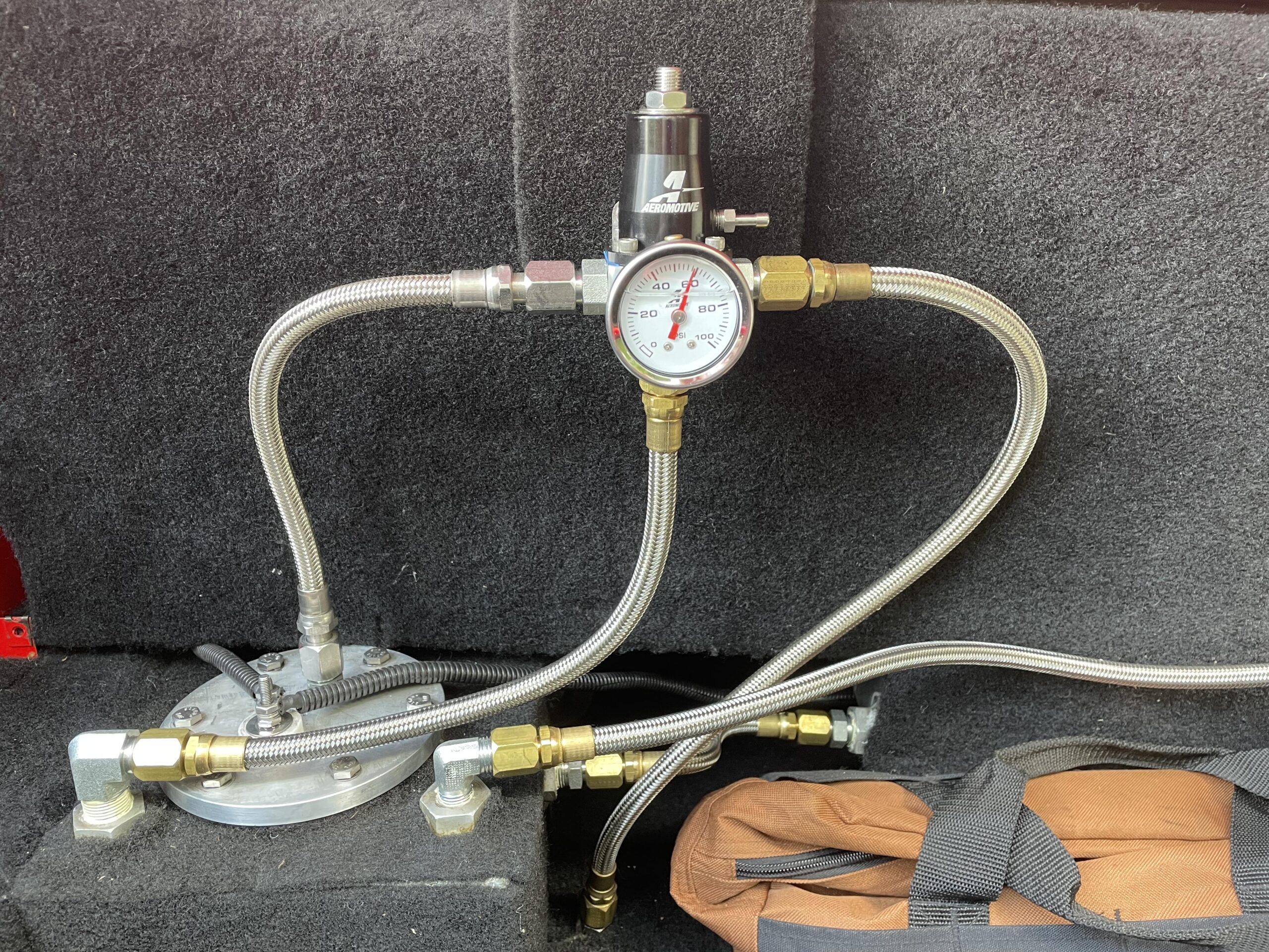
 On this 2023 July 4th weekend, bowtie6 got treated to a new fuel pressure regulator and braided lines. The old setup consisted of a GM style non-adjustable pressure regulator and a set of E85 resistant rubber fuel lines – I wrote an article about that (click here). I was never really pleased with the rubber hoses because the braided lines are much nicer and bullet proof. So I pulled the trigger and ordered parts for the new setup.
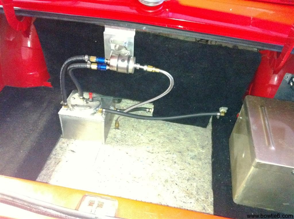
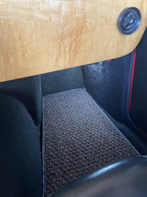
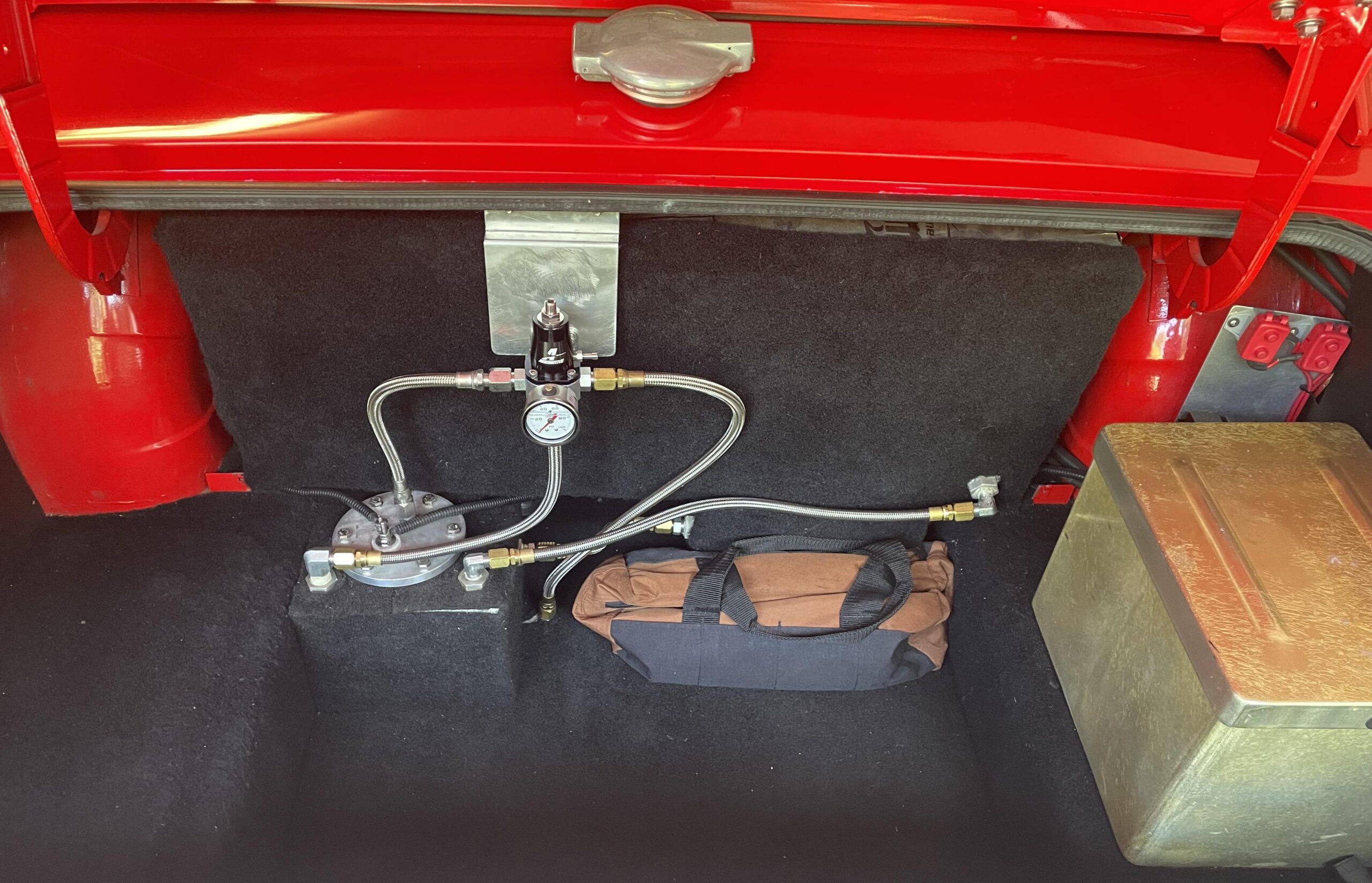 And this is what I mean…
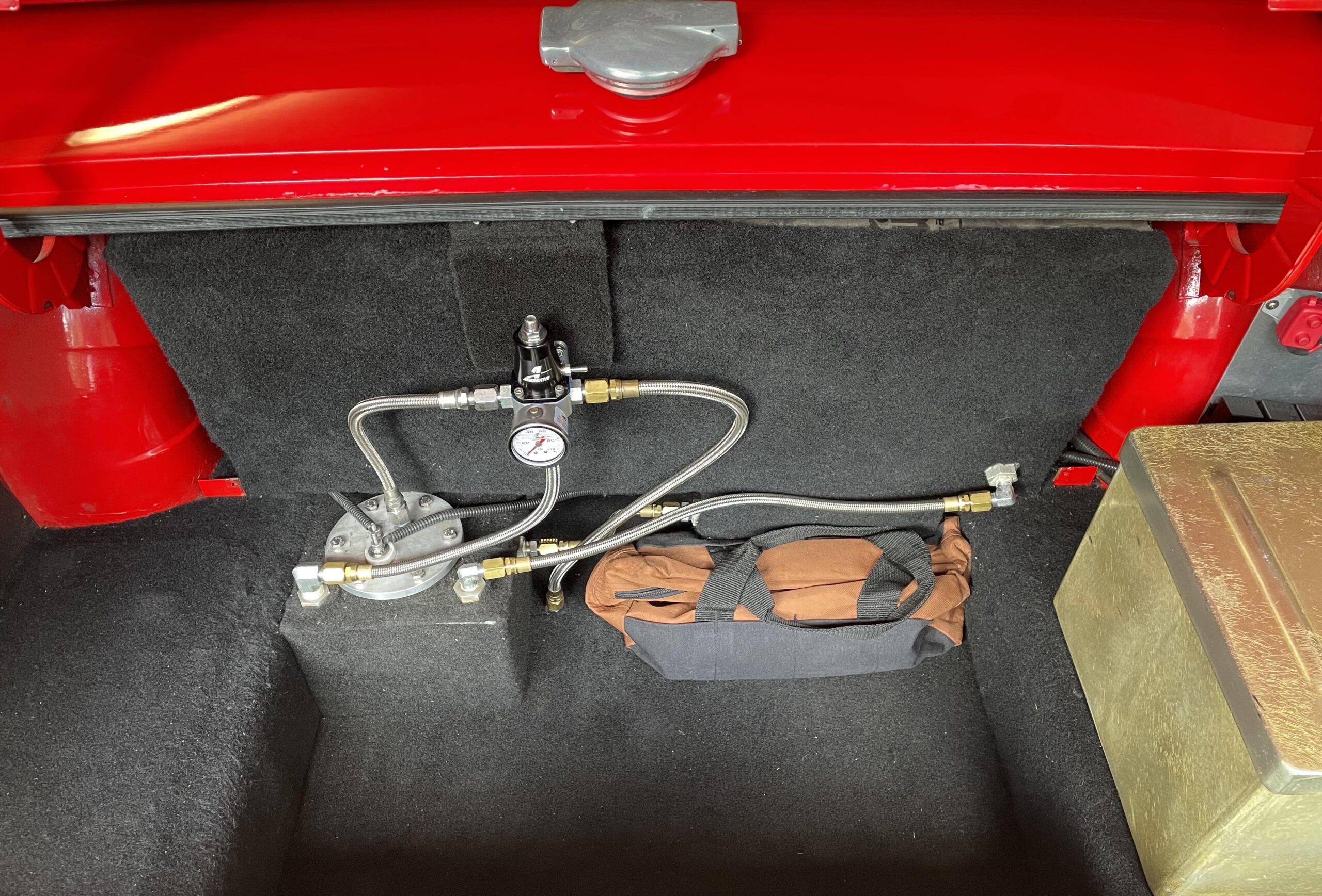
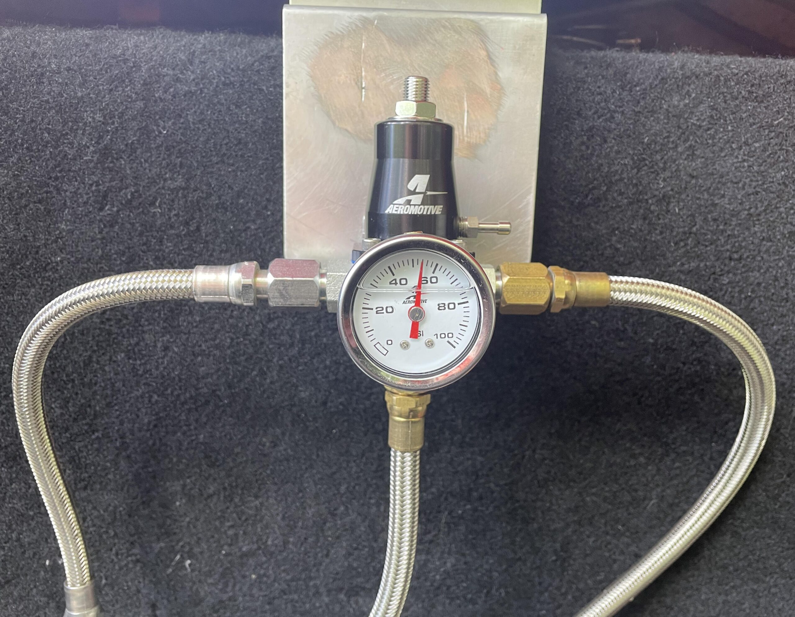 We had to cut the old mount and in the process the aluminum mount got scratched up pretty bad. I tried to sand this down but didn’t make much progress. Instead, why not just use some carpet material?
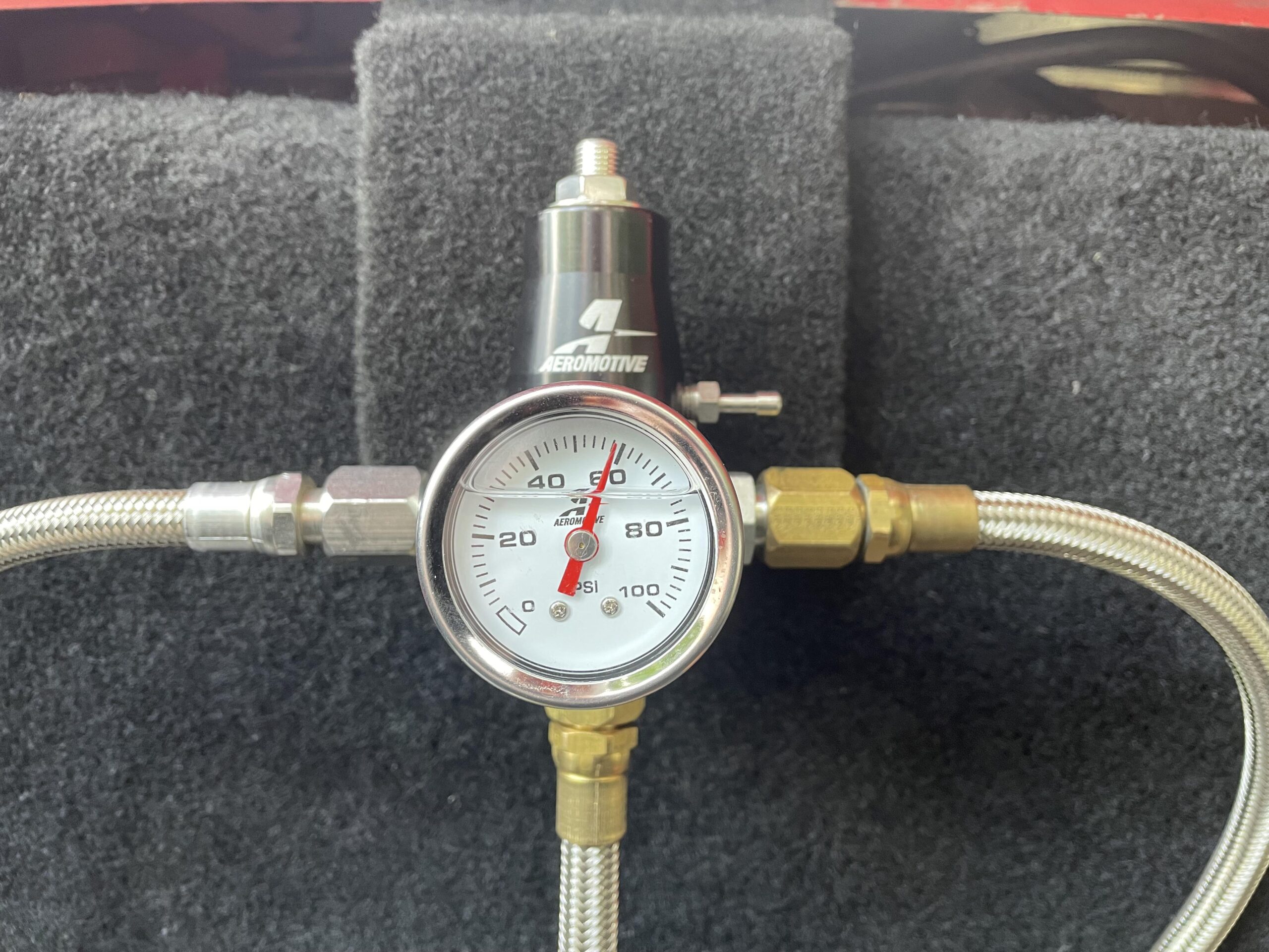 Ah! Much better! A keen eye will also notice the difference in pressure. I checked what the E67 PCM expected, and that was 58 lbs/in, so I bumped that up a bit.
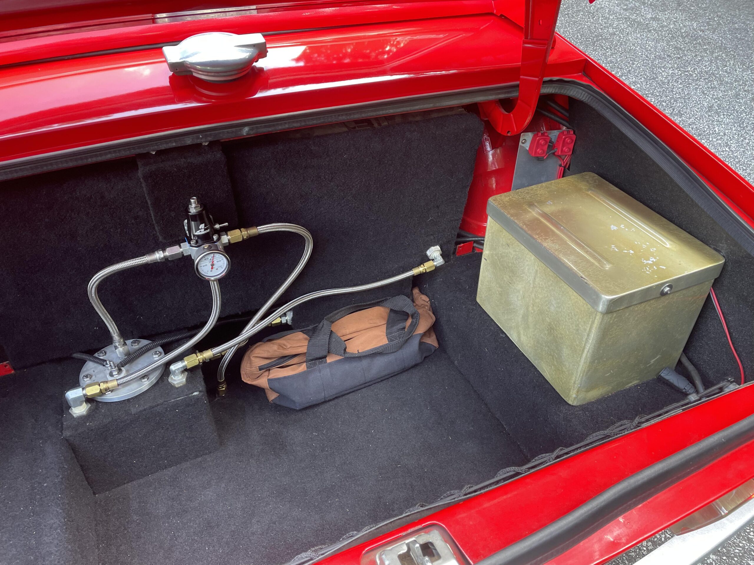
 And this is what the front looks like. This is another braided line going into the fuel rail. The other side connects to the stainless tubing under the frame of the car…