Monthly Archives: December 2011

Backfire!

Looks like 2011 ends in a bang.  Literally.

Yesterday morning the sun was out so I decided to take bowtie6 to work.  Unfortunately, I did not press the “Start” button long enough, the engine turned for just a split second and backfired when I let go of the button.  I’ve had this happen twice before with no serious consequences but this time, we had a problem: the “bang” cracked the intake.

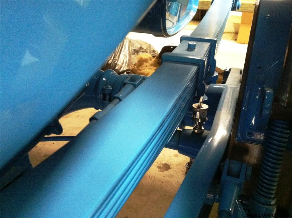
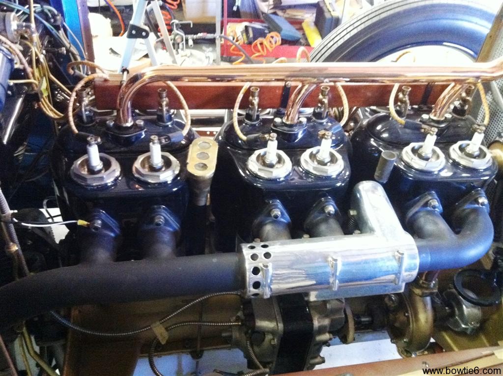
There is nothing wrong with the design of the intake or with anything else.  This was my mistake 100%.  I just call this a risk of running non-factory parts.  The new intake is all aluminium; this is what the intake looks like:

We had to make this intake up because there is no room for the original plastic intake.  Actually there is, but it would have required the steering column to be relocated bigtime and it was just not worth the trouble.  The intake you see above is made in several pieces.  The flange that bolts to the head came from GM Performance Parts and is water jet cut aluminium.  This all has to be made in pieces and welded in place as such.  The four intake runners are aluminium tubing, cut and bent to fit the oval ports on the GMPP flange.  They were welded to the flange from the outside otherwise there would be a lot of machining to make the flange perfectly flat again.

The runners then were fitted to a flat piece of aluminium which made the intake side of the long plenum on the top.  There was a bead ran on the inside of that plate.  Then, the rest of the plenum was shaped and welded in place.  The seams were filed smooth and it all looks like one solid piece.  Finally a flange was made and welded where the throttle body gets bolted with four screws.

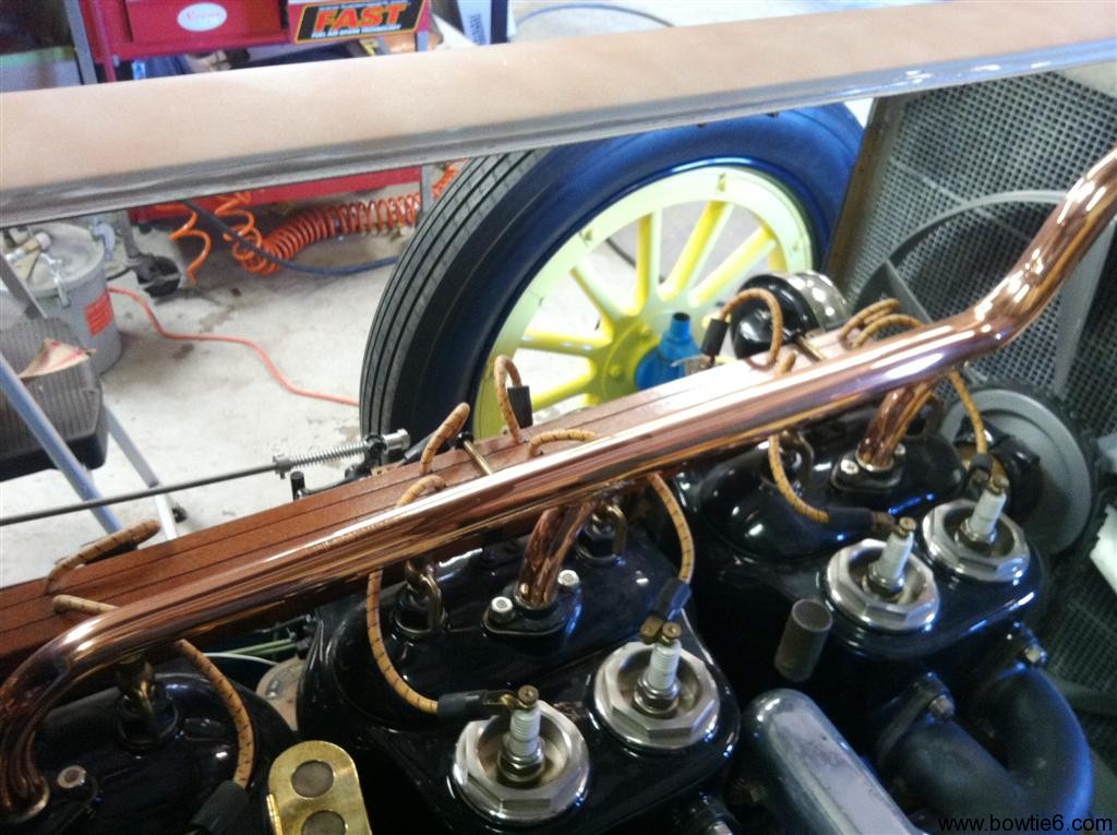
All good, except that the four runners ended up with a delicate bead around them, on the inside of the intake plenum.  So, when the backfired occurred it caused the seam on number 4 runner to assplode.  Take a look:

Obviously, it doesn’t take much for the thing to have a major vacuum leak and cause the engine to fail to run.  Needless to say, with this crack RPM’s went through the roof!  One interesting thing about all this is the ECM was smart enough to figure this out, and basically shut things down.

The outside of the runners needs to be welded again (duh!).  Had we not had the backfire, this would have not been a problem.  The seal has been flawless but unfortunately the thing just could not cope with the force of the assplosion.  As you can see, the intake has been removed and will be welded back today.  I hope to be back on the road hopefully tomorrow.

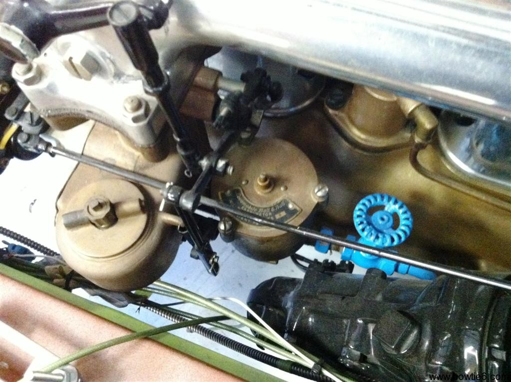
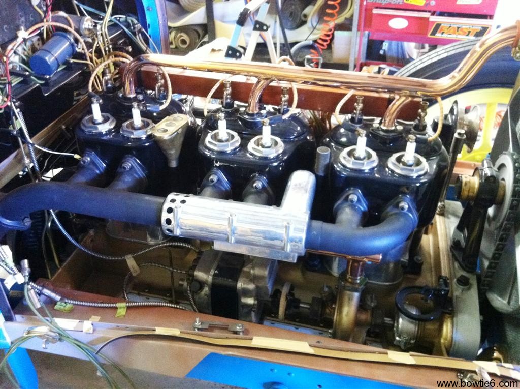
Here is a picture of engine-side of things:

Sorry for the picture being so dark, but you can see there is not much distance between the intake valves and the actual intake itself.  Not at all.  Also, the gasket seems out of place because it is not pushed all the way up against the head – in reality it fits perfectly with the intake opening.

No worries though – this should be a quick fix…  🙂


1917 Locomobile – Part 2

The rest of the Locomobile is pretty awesome too.  Here is a collection of pictures showing the interior and many other details on the Locomobile.

No, no ABS here.  This is the speedo sender.  Also notice the absence of front BRAKES!  The only brakes on this machine were on the back and they were these huge band affairs.  I don’t think this car would stop on a dime.  Matter of fact, I bet it took quite a long time to get it stopped.

Check out the flywheel on this machine!  It is not enclosed, the gear is helical cut so the starter has a better chance at engaging.

Take a look at the shine on the radiator surround.  This is not chrome, by the way.  This is nickle plated.  The entire car’s shiny parts were all nickle plated.  This stuff is amazing!

Next is a gallery of a few more details.  For you on the mailing list, do check out this post online – you will be missing out the photo gallery!

  • The springs on the rear suspension are twofold: 1) on the bottom is a full length spring, 2) on the top is a quarter elliptical.
  • Check out the fuel tank! Fuel gauge is mounted on top.
  • The fuel cap is screwed on.  The system is pressurized by a small hand activated pump on the dash.  Kinda like an old Coleman gas lantern.
  • All the doors are wood.  The frame is wood, has a turnbuckle on a cable to make them “fit”.  There is a metal skin folded over the wood frame.
  • The exhaust muffler is huge.  The thing is covered in what looked to be an asbestos blanket of some sort.

I mentioned above there are no front brakes.  Take a look at what stops this car.  These are the rear brakes…

Good Times…

I hope Santa was good to you all…

Santa was very good to bowtie6!!  Just had dinner, opened one of my Xmas presents and watching “To Catch a Thief”…  That blue Sunbeam was pretty darn awesome, but Grace Kelly in the white outfit and diamonds…  Dayum!

At any rate, this is what Santa brought me…

Good times indeed!

1917 Locomobile – Part 1

A Locomobile??

The Locomobile Company of America was founded in 1899 manufacturing affordable steam powered cars in Watertown, Massachusetts.  That lasted for a couple of years when they moved to Bridgeport, Connecticut and ditched the affordable cars for high-end luxury cars.  When I mean luxury cars, I’m talking high-end.  In 1919 a Locomobile open bodied car would sell for $10,000 while the proletarian Ford Model T sold for $300.

The pictures I am going to list here were taken at a local restoration shop.  We know the owner, matter of fact I bought bowtie6‘s ECOTEC engine and gearbox from him.  The Locomobile is there to have its upholstery completely restored including the enormous convertible top.  Finding all the material for the restoration has been a painstaking process requiring a special run of material made by the original manufacturer.  There will be no expense too high here…

There are so many details about this car.  I spent quite a bit of time looking it over, taking pictures and wondering.  Wondering where it had been, how many people it had carried and what roads and streets it had been driven on.  The 1920’s were full of excesses before the stock market imploded.  Wonder how many times this car was driven to swanky parties with occupants dressed to the hilt, “putting on the Ritz”?  Makes you wonder…

Obviously, the body has been painted and a lot of work has been done to the engine.  It is amazing.  However, there are so many intricacies raging from the engine, the wheels, the interior, dash, engine (oh my!) and well… Let me show you.

The engine is a side valve, inline six.  The piston jugs are finished in porcelain and each piston has 2 spark plugs.  There is copper and brass galore.  There is a magneto running power to each plug and each plug has a really interesting connector for the spark plug wire.

It looks like somebody must have spent a huge amount of time making the radiator.  The thing looks handmade.  The fan is pretty cool, with the outside ring around the blades.  And take a look at that fan belt.

On the exhaust side of the engine you can see a chrome heat riser for the carbs.  Down on the front side of the engine you can also see the water pump.  On the intake side of the engine, right behind the horn you can see the magneto and the bundle of fabric-covered spark plug wires.

This is an intriguing detail:

On either side of the copper tubing you can see two “valve” looking affairs on the engine head.  There were six of these, one for each cylinder.  Since this is an engine that was also set up to start by hand (there was a hand crank extension sticking through the front of the rediator), these are pressure relief valves.  Or, perhaps something to prime each cylinder with?

I’ll have more pics later…

bowtie6‘s Custom Wiring – Inside the Cab

The last and final installment of the bowtie6‘s custom wiring takes us to the inside of the cab.  This will be the last on wiring – I know this is getting boring but I just want to show what can be done with a little creative thinking.

So what do we have here?

The picture above shows the quilted maple dash we made, it is mounted to an aluminium backing dash which in turn is bolted to the stock TR6 mounts.  The vent is fully operational with a bit of a twist – I’ll have to write about this later…

Behind all this you can see what I call the “cab” wiring.  Here are two spade fuse housings holding 7 of 8 fuses.  The ones on the left side are constant “on”; the ones on the right are switched.  In the middle you can see four relays.  Here is a closeup:

Why the missing fuse?  I am not completely done with the interior wiring and this circuit will be used at a later date when I add the final details to the inside:  fully operational door activated interior lighting.

Relays & Fuses

Four relays are mounted on this plate.  They control the following:

  • Heater and windshield wipers.
  • Turn signals – one relay controls “left”; the other controls “right”.
  • Parking lights.

As with all the other switches, the heater and windshield wiper switches make “ground”.  They in turn activate the electromagnet on the relays.  The B+ to the electromagnet side of the relays are fed by the fuses on either side.  I did not use circuit breakers here, I just used the spade fuese.

The turn signals are controlled by a stock TR6 turn signal stalk.  The turn signals feed goes through a “blinker” switch and from there, a wire is sent forward to control the front signals and a matching wire is sent rearward to the back turn signals.

The same process is done for the parking lights.  The parking lights and headlights are both controlled by a universal park-light/headlight switch.  I bought this from the same supplier I bought all the wiring from and is commonly used in street rods.

Two banks of fuses flank the relays.  The left ones are constant “ON” and supply power to the ignition switch, ECM and dash clock.  Yes, we have a clock in bowtie6!  I’ll have a writeup on the VDO gauges soon.

On the right, the fuses are switched “ON”.  These fuses supply such things are the control side to the relays as well as instrumentation lights and such.

In Summary

Once again, I guess you must be saying “this guy has a lot of time on his hands”.  Then again I wanted to make this flawless and 100% reliable.  I imagine you are asking yourself if this can be “seen”.  Well, I made sure to hide this as best as possible.  You have to get on your knees to see the fuse panel.  If you don’t know about it, you will never see it.  Finally it is mounted high enough that it does not get in the way of your knees and/or feet.

Another great advantage about all this is that all three panels are very easily accessible.  If for some reason a fuse blows it can be easily found and replaced.  When I built bowtie6 the first time, the fuse panel was in one central location.  It was VERY difficult to get to and was not easily serviceable.  I made sure to make it this time very “user friendly”.

And Then There is More…

See anything “unusual” in the pictures above?  There are two small details that do not exist in a stock 1972 Triumph TR6.  See if you can spot them.

If not, stay tuned and there will be more about this soon…